Eureka AIR delivers breakthrough ideas for toughest innovation challenges, trusted by R&D personnel around the world.

Vehicle seat with a temperature control unit

Inactive Publication Date: 2009-10-01
HONDA MOTOR CO LTD +1
View PDF35 Cites 8 Cited by
  • Summary
  • Abstract
  • Description
  • Claims
  • Application Information

AI Technical Summary

Benefits of technology

[0006]In view of the above problems in the conventional method, the present invention has a first object to provide a vehicle seat with a temperature control unit to send a heated or cooled air smoothly to the best place of a seat. In order to achieve such an object, a vehicle seat with a temperature control unit related to the present invention is composed of a seat pad bearing a plurality of ditches on a surface of a seat pad, a blower to send a heated or cooled air to the surface of a seat pad, and a divergence department to send a heated or cooled air sent from the blower to a plurality of ditches, wherein it furnishes the first plate having non-breathability to cover a surface of a seat pad in a divergence department and the second plate having non-breathability to cover a surface of a plurality of ditches in a surface of a seat pad, and at the same time the second plate is composed of a vent making it possible to discharge a heated or cooled air from a plurality of ditches partially. It is preferable to keep flexibility both of the first plate and the second plate in order to follow the weight at the time of sitting of an occupant flexibly. Therefore, a divergence department surface of a seat pad is covered with the first plate having non-breathability, and a ditch surface of a seat pad corresponding to the sitting place of an occupant is covered with the second plate having a vent. Even if an occupant makes sitting in a seat, a ditch cannot be occupied by his weight and a divergence department is not filled with heat because of taking the structure mentioned above. Furthermore, a heated or cooled air is sent to the most suitable point of the second plate because a vent is established to the second plate. Additionally, a vent is arranged only on a necessary part of the second plate, and a ditch of other parts except a vent is covered with the second plate and a ditch of a divergence part is covered with the first plate respectively. Therefore, a heated or cooled air is sent to the end of a ditch effectively.
[0007]The present invention has a second object to provide the system to prevent a tear of an occupant detecting sensor by imposition of an occupant detecting sensor to the opening edge of a ditch because of his weight at the time of sitting of an occupant when a film-shaped occupant detecting sensor used for an occupant posture detection system installed in a passenger seat is arranged on a surface of a seat pad. As a film-shaped occupant detection sensor used for an occupant posture detection system installed in a passenger seat is arranged on a surface of a seat pad, the presence of the first plate and the second plate covered a surface of a ditch prevents a tear of an occupant detecting sensor by imposition of an occupant detecting sensor to an opening edge of a ditch because of his weight at the time of sitting of an occupant.
[0008]The present invention has a third object to provide the system to prevent a decline of appearance quality of a seat. The presence of the first plate and the second plate covered a ditch prevents a decline of appearance quality of a seat because of a fall of a trim cover made by a cloth to a ditch. (Japanese Patent Application No. 2008-090239)

Problems solved by technology

Therefore, as the constitution to maintain a ventilation in a ditch becomes complicated in this conventional method its cost rises, and moreover there is also a malfunction that its ventilation and transmission efficiency of a heated or cooled air is inferior.
Additionally, there is a fear that a decline of appearance quality of a seat occurs because a hollow based on a fall of a trim cover to a ditch is easy to be formed on a surface of a seat.

Method used


Image

  • Vehicle seat with a temperature control unit
  • Vehicle seat with a temperature control unit
  • Vehicle seat with a temperature control unit

Examples


Embodiment Construction

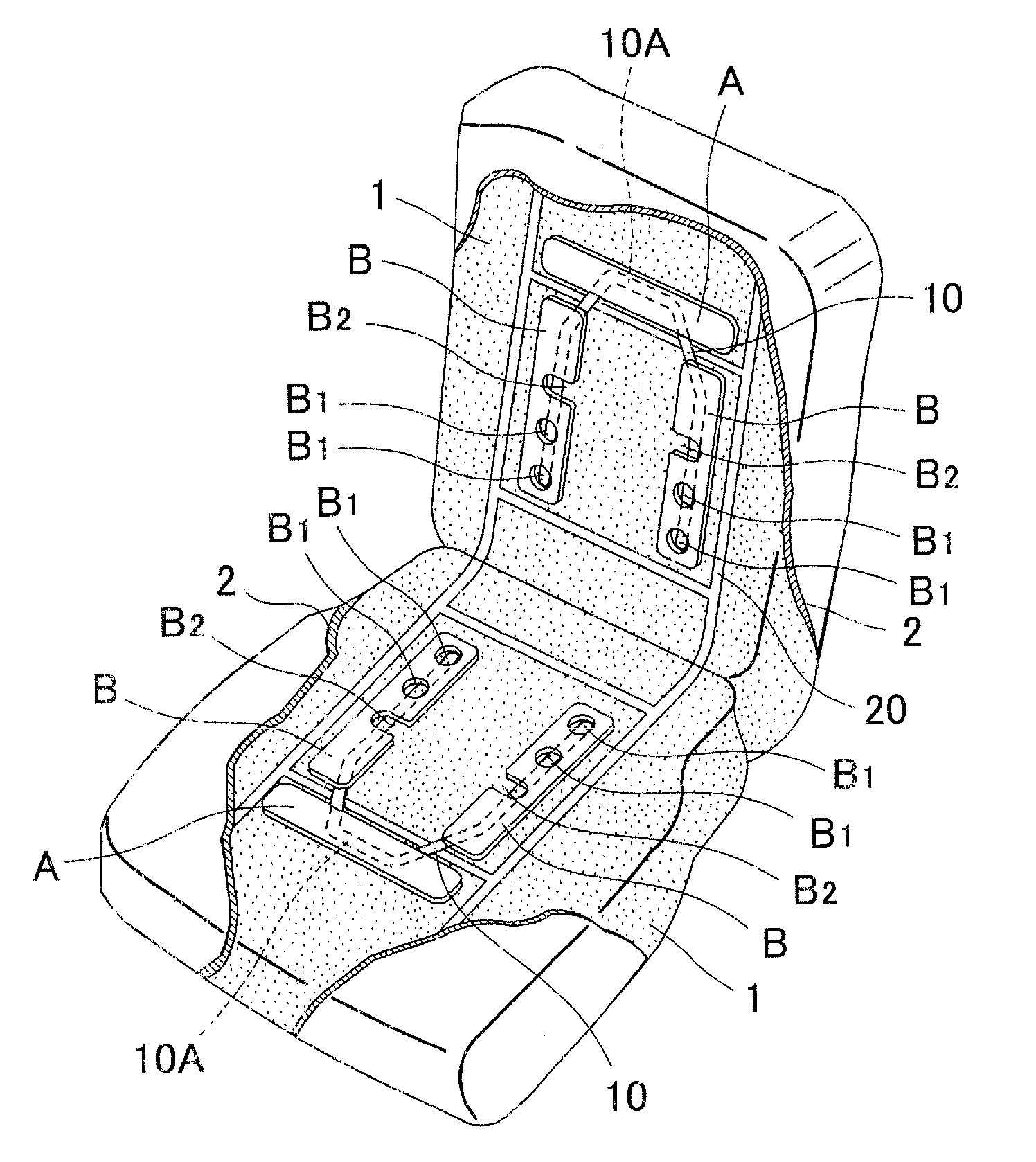
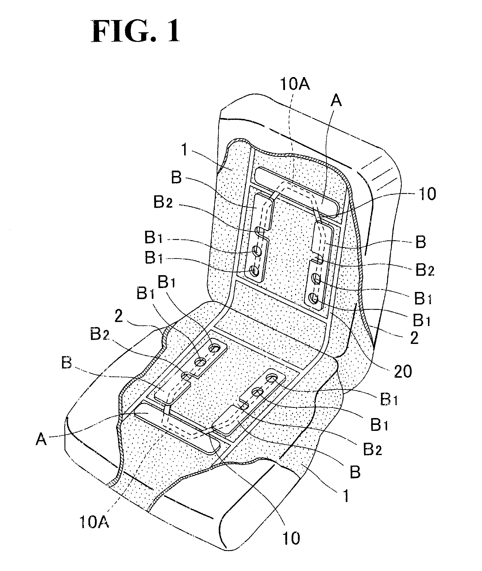
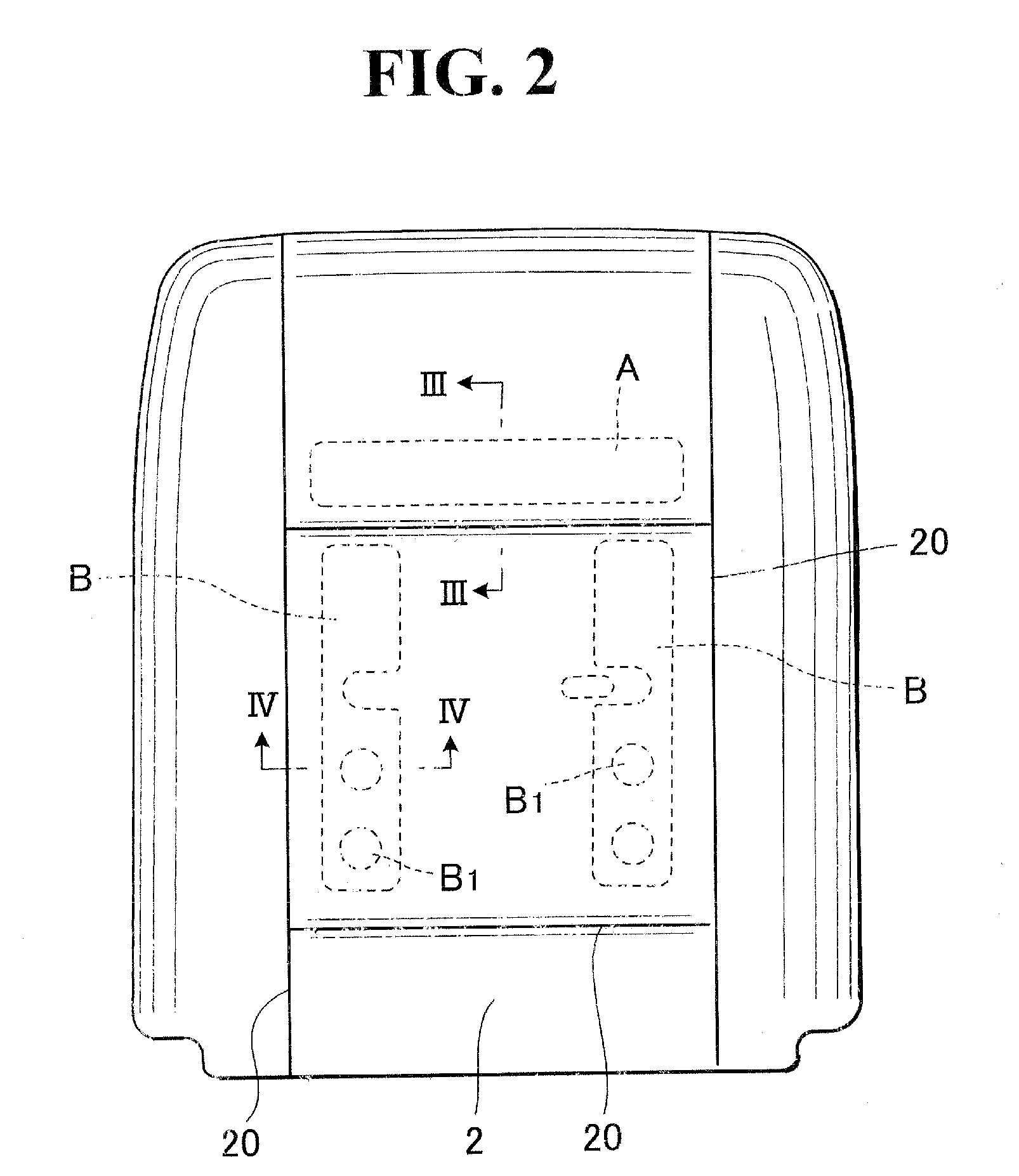
[0017]A vehicle seat with a temperature control unit related to the present invention is composed of a plurality of ditches (10) on a surface of a seat pad made by a foaming material covered by a trim cover (2) as seen from FIG. 1, a plurality of ditches (10) covered with the second plate 8 having vents (B1) - - - , and a divergence department (10A) in a plurality of ditches (10) to diverge a heated or cooled air sent from the blower (3) covered with the first plate A. A trim cover (2) is made by a cloth used for a vehicle seat with a temperature control unit having breathability. As seen from FIG. 3, a ventilation aperture (11) is made so that a heated or cooled air sent from the blower (3) installed in the back of a seat pad (1) is sent to a surface of a seat pad (1). Both of the first plate A and second plate B are composed of plates of non-breathability consisting of synthetic resin plates, for example polyethylene terephthalate (PET thickness: 0.25 mm), having flexibility that ...


PUM


Abstract

A vehicle seat with a temperature control unit is composed of a plurality of ditches installed on a surface of a seat pad covered with the second plate having a vent and a divergence department on a surface of a seat pad covered with the first plate, wherein the presence of a plurality of ditches on a surface of a seat pad and a divergence department to diverge a heated or cooled air sent from a blower to each ditch give good ventilation of a heated or cooled air.

Description

BACKGROUND OF THE INVENTION[0001]1. Field of the Invention[0002]The present invention relates to a vehicle seat with a temperature control unit, which sends a heated or cooled air from the back of a seat cushion or a seat back to the surface.[0003]2. Description of Prior Art[0004]Among various sorts of vehicle seats with a temperature control unit, there have been known a seat cushion and a seat back having a ditch on a surface of a seat pad made by a foaming material, wherein a heated or cooled air is sent from the blower located on the back of a seat back to a ditch through a ventilation aperture in a seat pad, and a heated or cooled air sent to a ditch is supplied from a trim cover bearing good breathability coating a seat pad to a surface of a seat cushion and a seat back (as disclosed from Japanese Unexamined Patent Application Publication No. 2001-327362 for example).[0005]In this conventional method a ditch is filled up by knitting in order to maintain good breathability, bec...

Claims


Application Information

Patent Timeline
IPC IPC(8): A47C7/72
CPCB60N2/002B60N2/5657B60N2/5635
Inventor NISHIDE, HARUTOMIMIYAGUCHI, MASATO
Owner HONDA MOTOR CO LTD
Why Eureka
Eureka Blog
Learn More