[0013]Meanwhile, in the outer peripheral insert, the wiper edge of the other single cutting edge adjacent to the radial outer peripheral side of a single cutting edge directed to the tip is formed in the shape of a straight line, and disposed so as to extend to a direction of the axis of the drill body. Thus, the inner wall surface of a
machining hole can be finished by the wiper edge, and thereby,
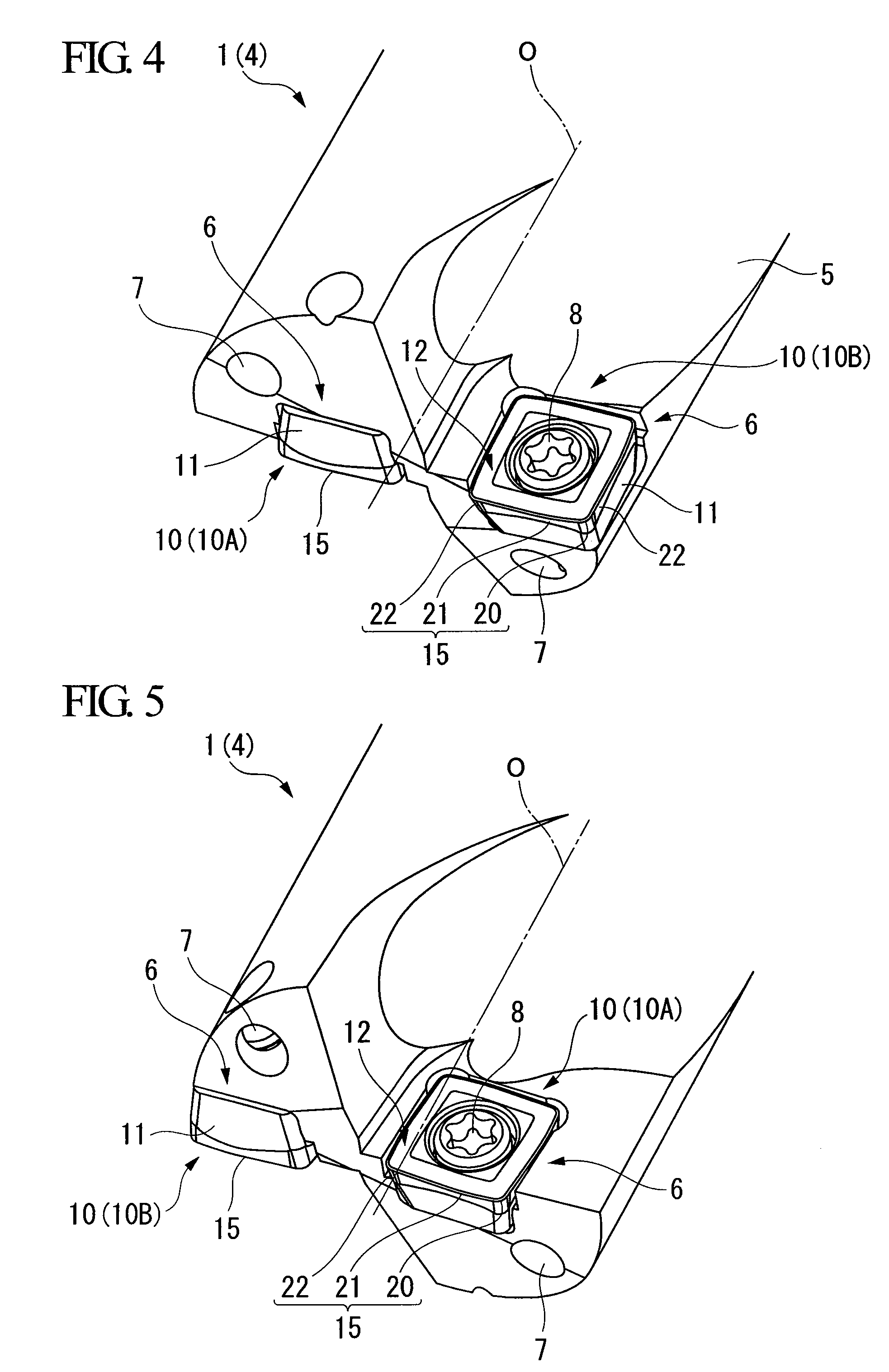
high surface quality can be secured in the inner wall surface. Moreover, since the wiper edge and the second major cutting edge portion of the major cutting edge is disposed in a direction in which they intersect each other at an obtuse angle, the intersection portion does not interfere with the inner wall surface of a machining hole.
[0015]Additionally, the length of the convex curve chord formed by the first major cutting edge portion is set to the range of 0.3×IC to 0.7×IC with respect to the
diameter IC of a circle inscribed in this rake face, in plan view. If the length of the chord is smaller than this range, the circular-arc first cutting edge portion becomes small in the major cutting edge. Therefore, there is a possibility that a loss may occur at the time of contact to a work material. On the other hand, if the length of the chord is greater than this range, the distance of protrusion from the imaginary plane of the first major cutting edge portion toward the tip becomes large in the inner peripheral insert. Therefore, the distance by which only the inner peripheral indexable insert drills a work material at the time of contact also becomes large. Thus, balance is upset, and radial run out also occurs easily.
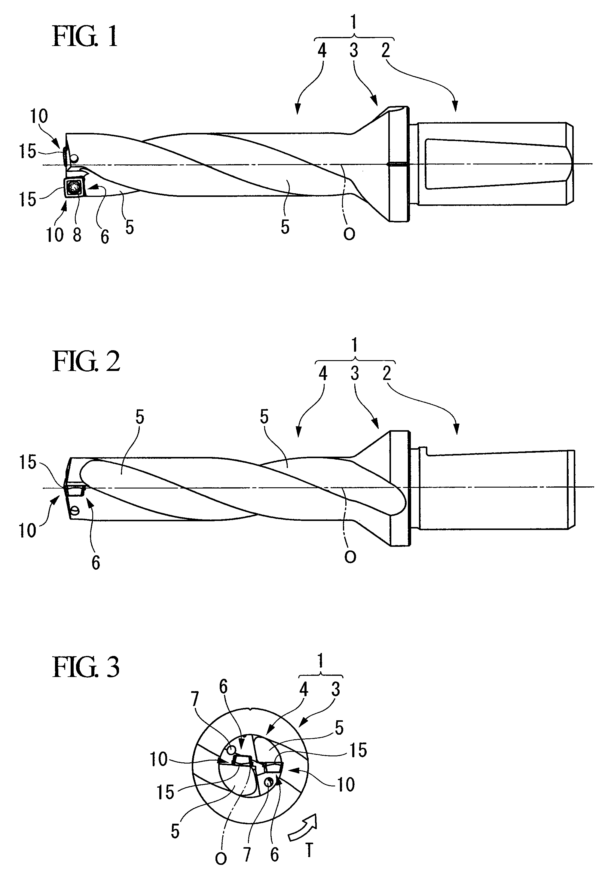
[0018]Meanwhile, in the indexable insert drill of the second aspect of the invention, preferably, the distance in the direction of the axis of the drill body between a protruding end of the first major cutting edge portion of the single cutting edge in the direction of the axis of the drill body in the inner peripheral insert, and an extreme end of the wiper edge of the single cutting edge in the direction of the axis of the drill body in the outer peripheral insert is set to 0.05 mm to 0.3 mm. If the distance is smaller than the above range, and if the amount of feed of the drill body is large, the wiper edge of the single cutting edge directed toward the tip of the outer peripheral insert is greatly involved in cutting, whereby wear or the like occurs, there is a possibility that the wiper edge cannot be used for finishing of the inner wall surface of a machining hole. On the other hand, if the distance is greater than this range, the distance of protrusion of the first major cutting edge portion in the inner peripheral insert becomes large. As a result, there is a possibility that the distance by which only the inner peripheral indexable insert drills a work material at the time of contact also becomes long, and thus, radial run out also occurs easily.
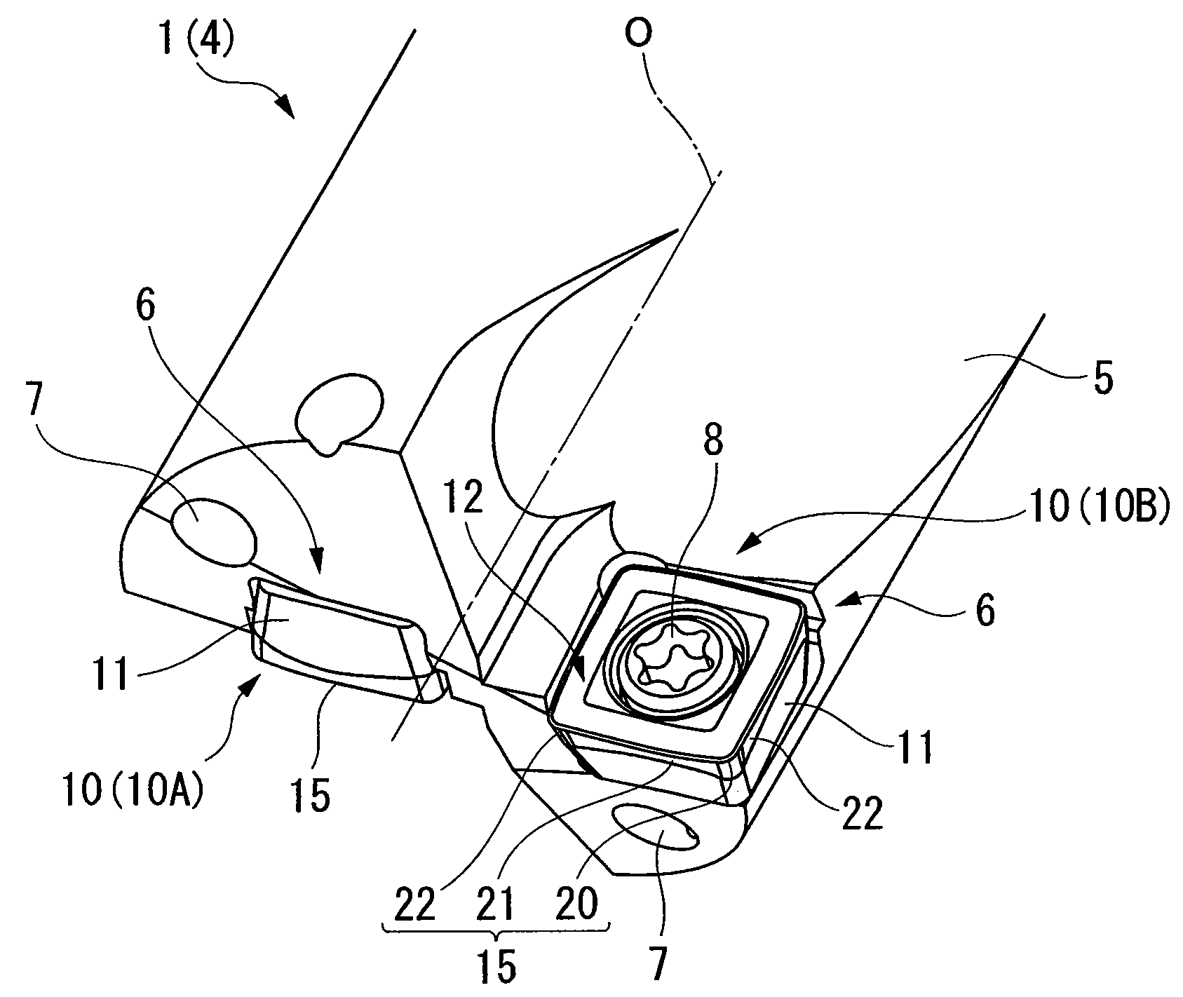
[0019]Preferably, the second major cutting edge portion of the single cutting edge in the radial inner peripheral insert is made to intersect the imaginary plane at an intersection angle of 3° to 8°. If the intersection angle is too small, the straight second major cutting edge portion contacts a work material largely along with the first major cutting edge portion at the time of contact, whereby radial run out may easily occur. On the other hand, if the intersection angle is too large, there is a possibility that the portion of the first major cutting edge portion of the major cutting edge on the side of the corner cutting edge in the single cutting edge of the inner peripheral insert, or the corner cutting edge itself is greatly involved in cutting at the time of contact or at the time of drilling, whereby a loss may easily occur.
[0021]As described above, according to the insert for a drill of the first aspect of the invention and the indexable insert drill of the second aspect to which this insert is attached, a loss does not occur in the cutting edges at the time of contact with a work material, the lifespan of an insert can be extended, and smooth drilling can be performed. Additionally, radial run out can be prevented from occurring in the drill body at the time of contact, and the inner wall surface of a machining hole can be finished with
high surface quality. Thus, it is possible to form a machining hole which has excellent roundness, concentricity, and cylindricity, and has a high
degree of precision. Additionally, since an insert for a drill with an insert body of the same dimension and shape is attached to inner and outer peripheries of the tip of the drill body, insert management can be simplified and efficient.

