Check patentability & draft patents in minutes with Patsnap Eureka AI!

Transmission method, wireless base station, and wireless communication method

Inactive Publication Date: 2009-10-01
FUJITSU LTD
View PDF4 Cites 27 Cited by
  • Summary
  • Abstract
  • Description
  • Claims
  • Application Information

AI Technical Summary

Benefits of technology

[0012]In view of the foregoing, it is an object of the present invention to provide a transmission method, a wirel

Problems solved by technology

However, if a plurality of cells (particularly adjacent cells) use the same frequency band, an interference can occur.
The method described in “Mobile WiMAX—Part I: A Technical Overview and Performance Evaluation”, WiMAX Forum, 2006-08, however, has poor radio transmission efficiency.
However, it is difficult to have coordination between the external zone and the internal zone, and the communication control efficiency is low.
This makes it difficult to allocate a frequency band in a flexible manner in accordance with the actual quality of communication.

Method used


Image

  • Transmission method, wireless base station, and wireless communication method
  • Transmission method, wireless base station, and wireless communication method
  • Transmission method, wireless base station, and wireless communication method

Examples


first embodiment

[0051]A first embodiment will be described below in detail with reference to figures.

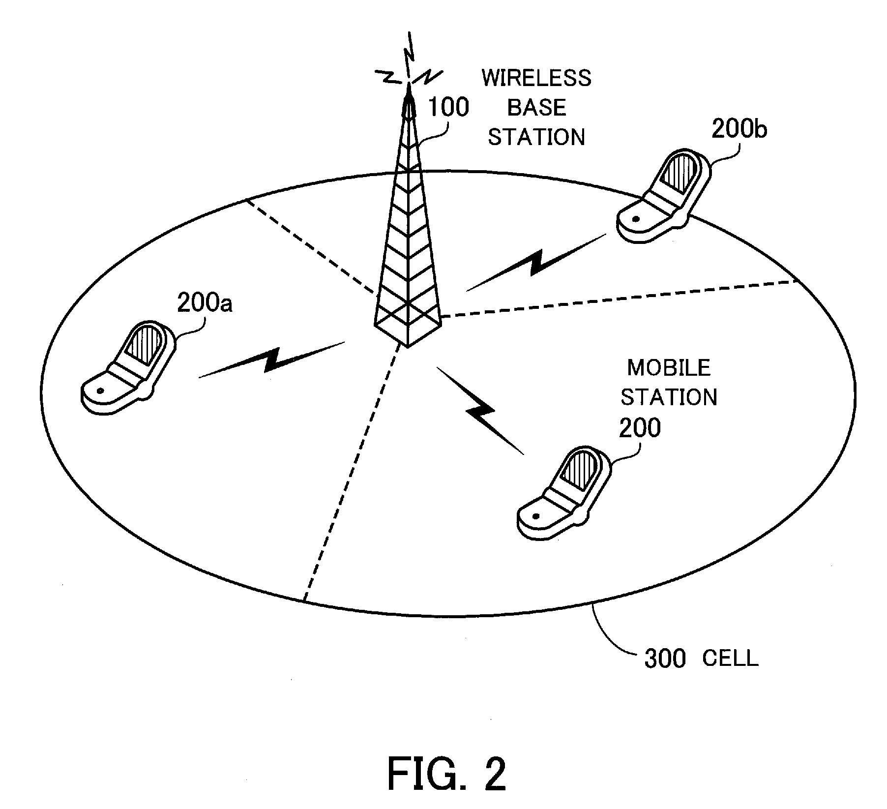
[0052]FIG. 2 shows the structure of a mobile communication system of the first embodiment. In the shown mobile communication system, a wireless base station performs wireless communication with a plurality of mobile stations. The mobile communication system of the first embodiment includes a wireless base station 100 and mobile stations 200, 200a, and 200b.

[0053]The wireless base station 100 is a communication apparatus that performs wireless communication with the mobile stations 200, 200a, and 200b. The wireless base station 100 forms a cell 300 as its service area.

[0054]The mobile stations 200, 200a, and 200b are wireless terminals that can perform wireless communication with the wireless base station 100.

[0055]In data transmission between the wireless base station 100 and the mobile stations 200, 200a, and 200b, the orthogonal frequency division multiplexing access (OFDMA) method is used, for e...

second embodiment

[0124]A second embodiment will be described in detail with reference to figures. Differences from the first embodiment will be described mainly, and the description of similar items will be omitted.

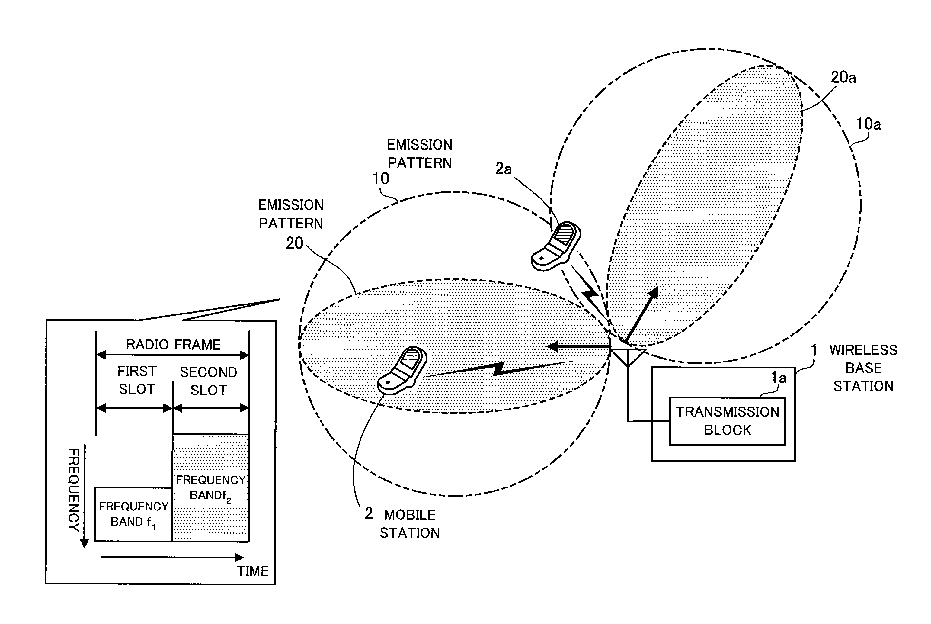
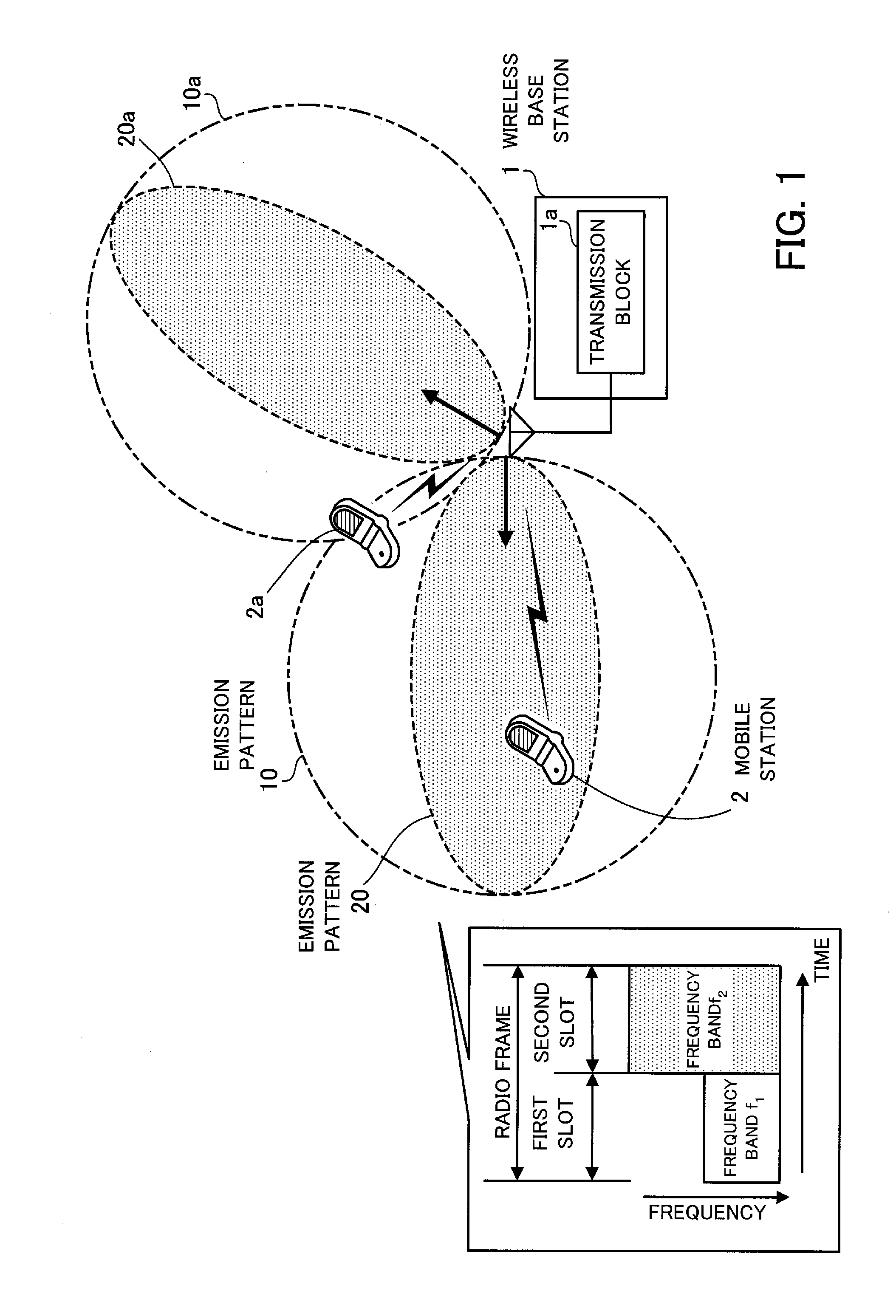
[0125]In the second embodiment, a wireless base station uses an adaptive array antenna to emit radio waves. The adaptive array antenna is an array of antennas and allows the directivity to be switched dynamically when emitting radio waves. With the adaptive array antenna, the radio quality at a reception point can be improved by emitting radio waves in such a manner that the degree of directivity is maximized in the direction of the reception point and by providing a null point where the degree of directivity drops in the direction of interference wave.

[0126]A mobile communication system of the second embodiment has the same structure as the mobile communication system of the first embodiment shown in FIG. 2, and a description of the structure will be omitted. The cell and sector structur...


PUM


Abstract

A transmission method that can implement efficient communication control. A transmission block sends a signal of a first frequency band allocated to each zone, by a first directive beam which covers the entire zone, in a first time slot of a predetermined period and sends a signal of a second frequency band which contains the first frequency band and has a greater width than the first frequency band, by a second directive beam which covers a part of the zone and has a smaller beam width than the first directive beam, in a second time slot of the predetermined period.

Description

CROSS-REFERENCE TO RELATED APPLICATIONS[0001]This application is based upon and claims the benefits of priority from the prior Japanese Patent Application No. 2008-092629, filed on Mar. 31, 2008, the entire contents of which are incorporated herein by reference.BACKGROUND OF THE INVENTION[0002]1. Field of the Invention[0003]The present invention relates to transmission methods in one or more wireless base stations, wireless base stations, and wireless communication methods.[0004]2. Description of the Related Art[0005]The present cellular mobile communication system divides a service area into a plurality of cells, where wireless base stations serving there are placed. In the interest of communication capacity, the frequency band that can be used in each cell of the cellular system should be as broad as possible. However, if a plurality of cells (particularly adjacent cells) use the same frequency band, an interference can occur. To implement communication of good quality, the same f...

Claims


Application Information

Patent Timeline
IPC IPC(8): H04W40/00
CPCH04W72/082H04W72/046H04W72/541
Inventor SUGA, JUNICHI
Owner FUJITSU LTD
Features
  • R&D
  • Intellectual Property
  • Life Sciences
  • Materials
  • Tech Scout
  • Unparalleled Data Quality
  • Higher Quality Content
  • 60% Fewer Hallucinations
Learn More