Underbody convective blanket and method for manufacturing thereof

a blanket and convective technology, applied in the field of convective blankets, can solve the problems of substantial reduction of the warmth of the air, the blanket is not meant to provide warmth to the head of the patient,

Inactive Publication Date: 2009-10-01
SMITHS MEDICAL ASD INC
View PDF12 Cites 49 Cited by
  • Summary
  • Abstract
  • Description
  • Claims
  • Application Information

AI Technical Summary

Benefits of technology

[0015]So that a surgeon operating on the patient is not heated by the warm air, another embodiment of the blanket of the instant invention eliminates a number of air apertures along the longitudinal channels that sandwich the non-inflatable body area of the blanket. In this embodiment, the respective rows of apertures that extend along the

Problems solved by technology

However, the '501 blanket is not meant to provide warmth to the head of the patient via convection.
This means that by

Method used


Image

  • Underbody convective blanket and method for manufacturing thereof
  • Underbody convective blanket and method for manufacturing thereof
  • Underbody convective blanket and method for manufacturing thereof

Examples


Embodiment Construction

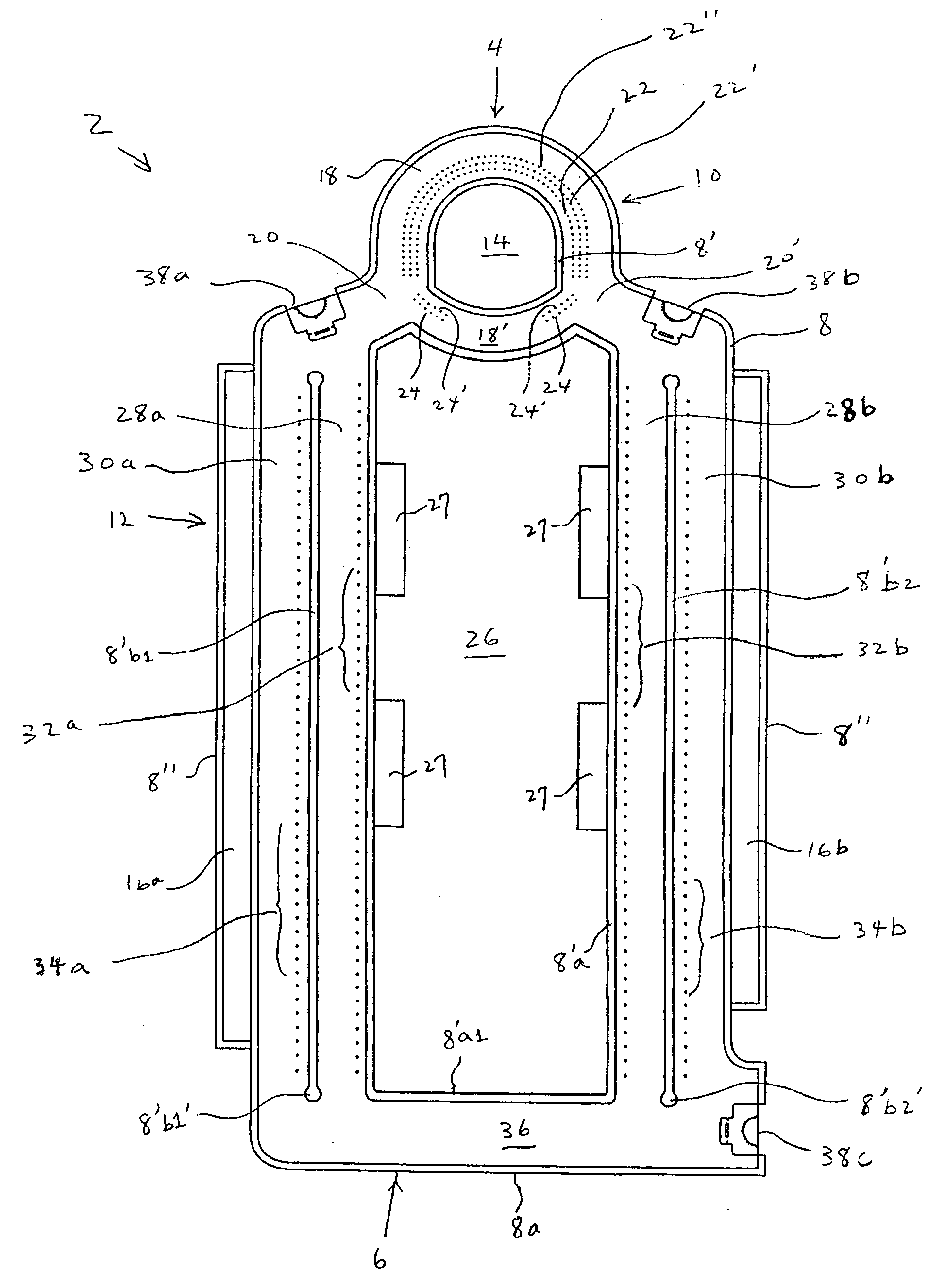
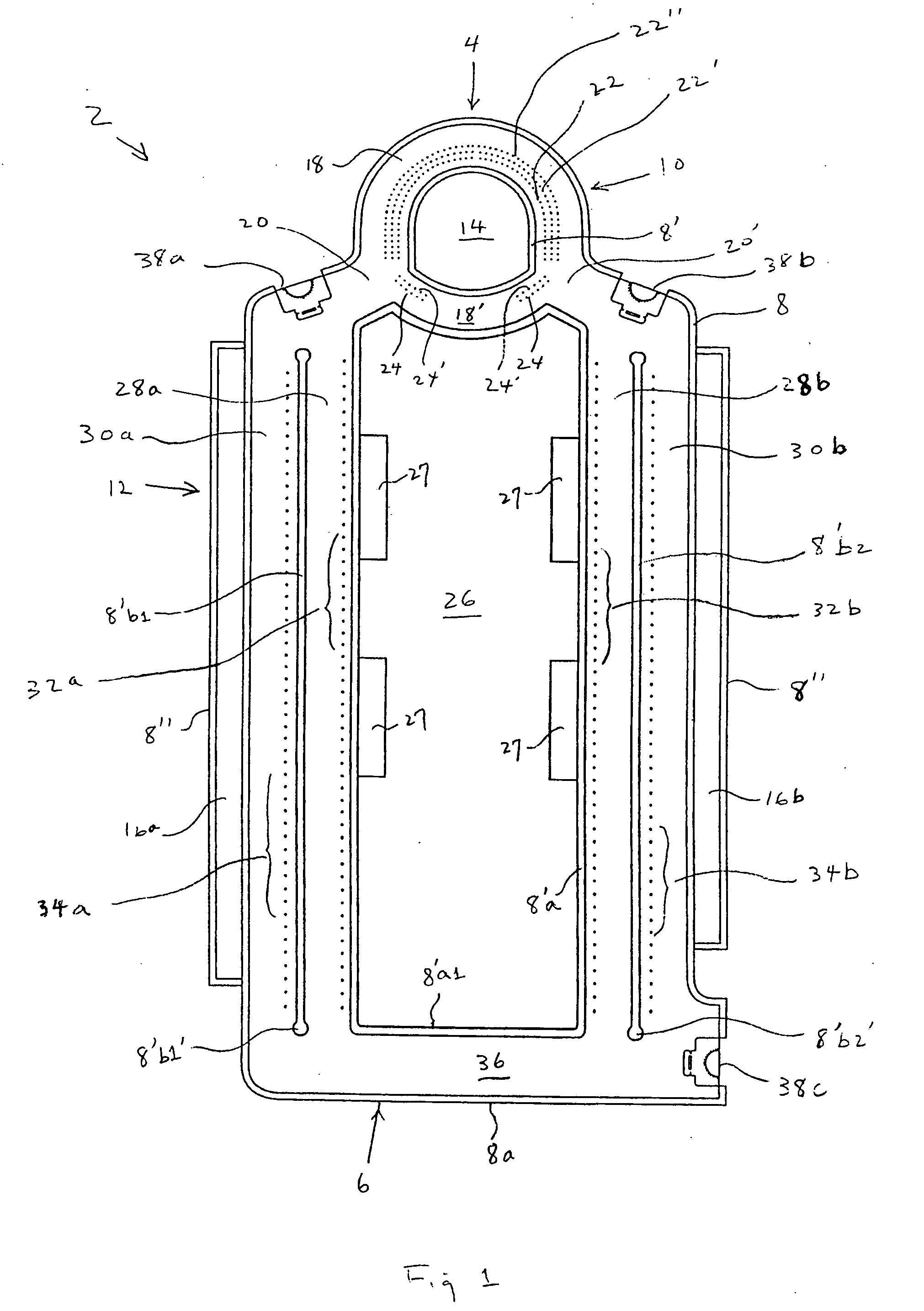
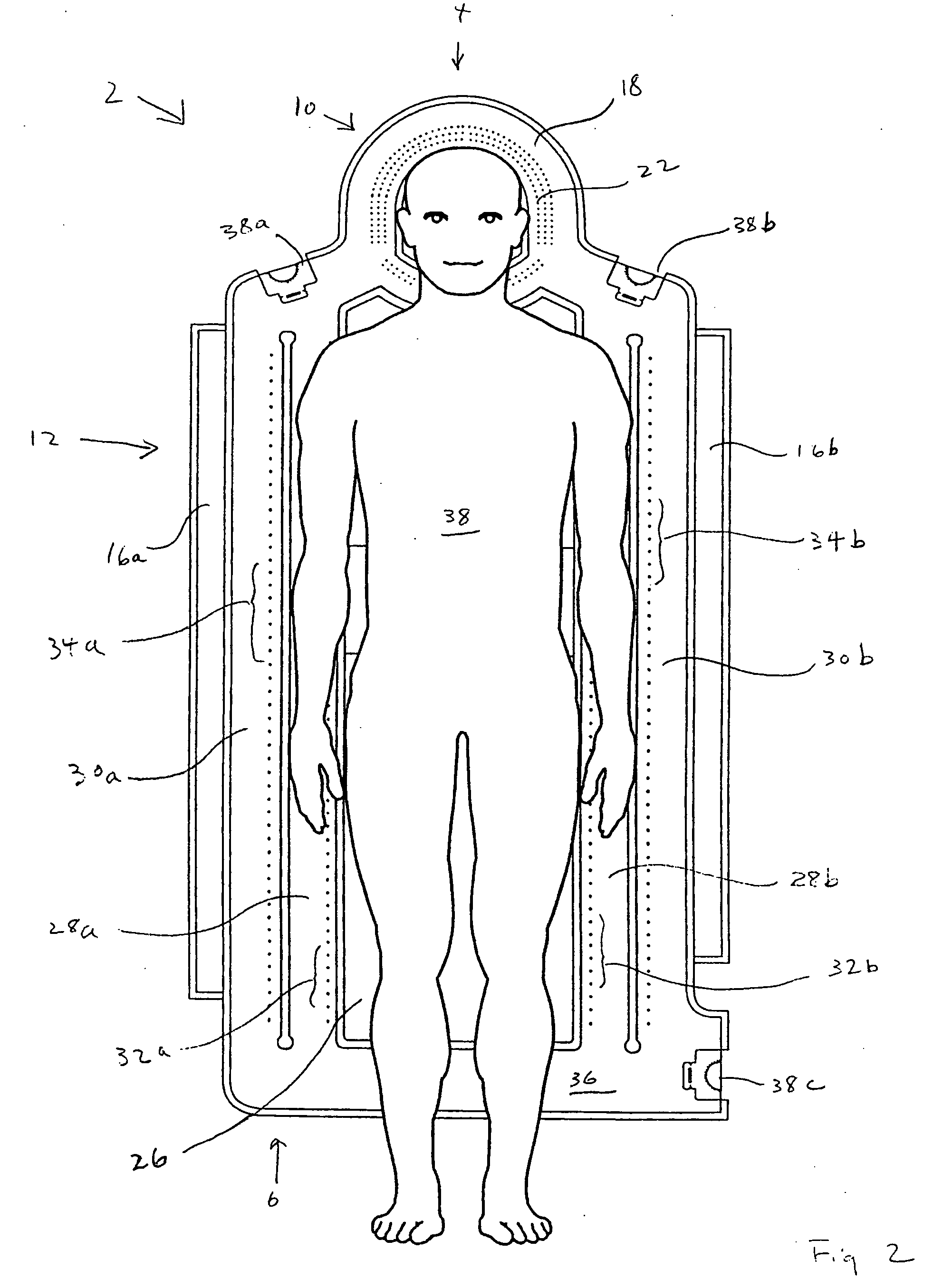
[0028]With reference to FIG. 1, a convective underbody blanket 2 is shown to have a head end 4 and a foot end 6. The blanket is made of two sheets of flexible air impermeable material that are bonded together. The bonding of the first or top flexible air impermeable sheet to the second or bottom flexible air impermeable sheet is done by seals such as 8, 8′ and 8″ shown. Seal 8 designates the outer seal that forms the outer periphery of blanket 2. Seal 8″ designates the seals that, together with seal 8, form the outer flaps 16a and 16b of the blanket. Seal 8′ designates the internal seals of the blanket. Thus bonded, the flexible air impermeable sheets form blanket 2 that has a head portion 10 and a body portion 12.

[0029]In head portion 10 there is a non-inflatable head sub-portion, or area 14. Non-inflated head area 14 is surrounded by a channel 18 that has two openings 20 and 20′. It should be appreciated that even though only one channel 18 (which includes to be discussed lower ch...


PUM


Abstract

A convective underbody blanket has a head portion and a body portion. Provided at the head portion is a non-inflatable head area surrounded by a channel that has arranged thereat at least one row of air apertures that are oriented toward the non-inflatable head area when the channel is inflated. At the body portion there is provided a non-inflatable body area. Along each longitudinal side of the body area there is at least one longitudinal channel. Each of the longitudinal channels is in fluid communication with the channel that surrounds the non-inflatable head area. The longitudinal channels that sandwich the non-inflatable body area extend substantially along the length of the non-inflatable body area and are in fluid communication with each other by way of a cross channel formed at the foot end of the blanket. The configuration of the blanket allows air input to the blanket to be circulated through the various channels, so that the heated air output from the different rows of apertures formed at the various channels has substantially the same temperature. The different rows of apertures may be provided at different areas along the blanket.

Description

FIELD OF THE INVENTION[0001]The present invention relates to convective warming blankets and more particularly to an underbody blanket for convectively warming both the head and the body of the patient.BACKGROUND OF THE INVENTION[0002]There are underbody convective blankets in the market. One of those blankets is described in U.S. Pat. No. 6,511,501. However, the '501 blanket is not meant to provide warmth to the head of the patient via convection. There are moreover a number of other blankets represented for example by U.S. Pat. Nos. 5,360,439, 5,384,924, 5,514,169, 5,632,769 and 5,839,133 that specifically have a recess at the head end of the blanket whereby the head of the patient lies.[0003]There are some convective blankets that could warm the head of the patient. However, most of those blankets are for covering the body of the patient. An example of such blankets is disclosed in U.S. Pat. No. 5,928,274 in which the head portion of the blanket has a recess so that only the head...

Claims


Application Information

Patent Timeline
IPC IPC(8): A61F7/00A47C21/04
CPCA61F2007/006A61F2007/0001Y10T156/1062A61F2007/0059A61F7/00A61F2007/0091Y10T156/1057A61F2007/0288A61F7/0097
Inventor STARR, RACHELPIERRE, JOSEPHREARDON, DANIELSTEC, ALAN
Owner SMITHS MEDICAL ASD INC
Why Eureka
Try Eureka