Shielded plug-in connector

a plug-in connector and shielding technology, applied in the direction of electrically conductive connections, coupling device connections, electrical apparatus, etc., can solve the problem of not being able to effectively shield the known type of connections

Inactive Publication Date: 2002-10-29
LAPPOHN JURGEN
View PDF6 Cites 78 Cited by
  • Summary
  • Abstract
  • Description
  • Claims
  • Application Information

AI Technical Summary

Problems solved by technology

For shielding individual contact elements which are, in particular, arranged in multiple rows and, moreover, in a multi-pole plug-in connector provided for the aforemention

Method used


Image

  • Shielded plug-in connector
  • Shielded plug-in connector
  • Shielded plug-in connector

Examples


Embodiment Construction

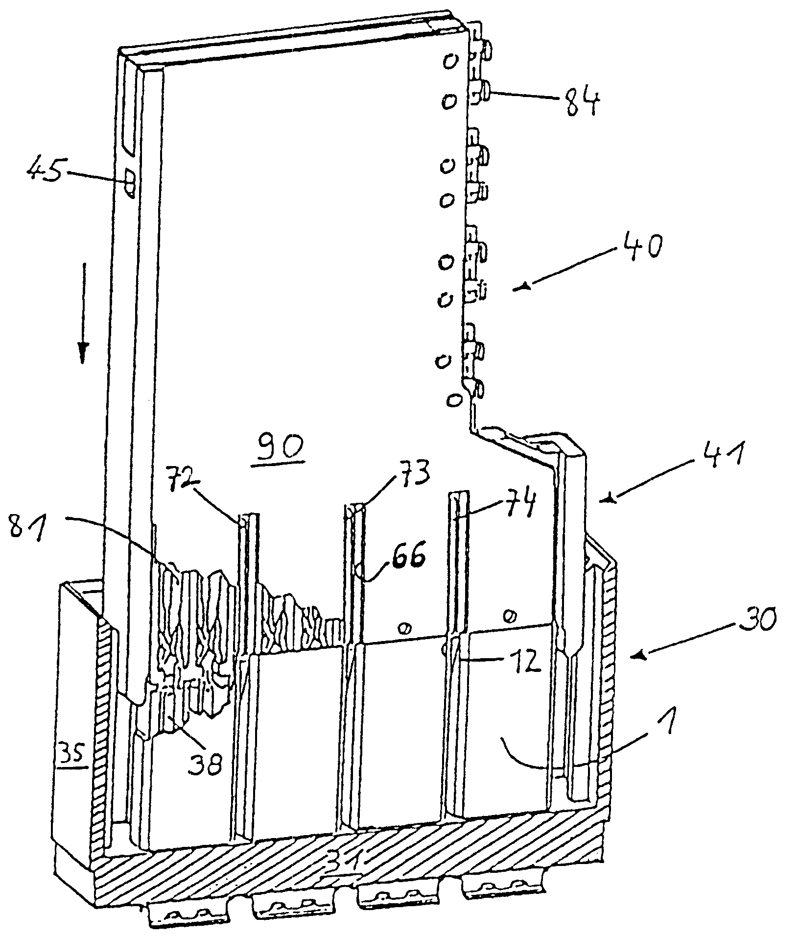
In FIG. 1, the new shielded plug-in connector is shown in an embodiment of a jack-in-blade strip / edge connector during plugging in of the edge connector 40 onto contact pins of the jack-in-blade strip 30. For improved illustration, the edge connector 40 in this illustration is sectioned transversely. An upper cover 90 of the edge connector 40 is partially broken away in FIG. 1, also a back wall of the base parts 1 so that in this illustration the position of the contact pins 38 and of the contact springs 80, in particular, their front spring part 81, can be seen. The terminal tabs of the contact springs of the edge connector 40 are identified by 84. The jack-in-blade 30 is comprised in a manner known in the art of a socket 31, sidewalls 34 and 35, as well as a front wall and back wall which are connected with the sidewalls 34, 35 and the socket 31 in a positive-locking way. For the purpose of material and weight savings, the sidewalls, front wall, and back wall are of a thin wall co...


PUM


Abstract

A shielded plug-in connector has a jack-in-blade strip having at least one first contact element and an edge connector having at least one second contact element corresponding to the first contact element. The edge connector, on or in its outer body areas, has at least partially shielding sheets. Shielding of the plug-in connector is achieved by, in addition to the shielding sheets provided on the edge connector, a shielding group with at least one first element arranged in the jack-in-blade strip. The first element of the shielding group is a base part in the form of a U-shaped rail. The shielding sheets on the edge connector have a planar body and angled stays. Two of the angled stays and a portion of the planar body between the two angled stays form a counterpart to the base part, wherein the counterpart and the base part together substantially encapsulate the first and second contact elements.

Description

1. Field of the InventionThe invention relates to a shielded plug-in connector, in particular, a multi-pole, single-row or multi-row plug-in connector, preferably comprised of a jack-in-blade strip and an edge connector, with which electrical lines, in particular, lines of electronic components or assemblies, in particular, circuit boards, are connected with one another, preferably in a detachable way.2. Discussion of the Related ArtIn known plug-in connectors shields for a single-pole or also multi-pole plug-in connector are designed such that the plug part and / or the socket part, the jack-in-blade and / or the edge connector, are provided with large surface area shielding sheets mounted externally or internally on their housing parts. This type of shielding is effective for interference signals that act from the exterior on the plug part. For shielding individual contact elements which are, in particular, arranged in multiple rows and, moreover, in a multi-pole plug-in connector pro...

Claims


Application Information

Patent Timeline
IPC IPC(8): H01R12/00H01R12/16H01R13/648H01R12/50H01R13/514
CPCH01R23/688H01R23/7073H01R12/724H01R13/6585
Inventor LAPPOHN, JURGEN
Owner LAPPOHN JURGEN
Why Eureka
Try Eureka