Blade tip coating that can be rubbed off

a blade tip and coating technology, applied in the direction of coatings, pressure inorganic powder coatings, air transportation, etc., can solve the problems of affecting the functionality of the running-in layer, reducing the flexibility of material selection, and reducing the cost of manufacturing. , to achieve the effect of reducing manufacturing costs, reducing manufacturing costs, and reducing manufacturing costs

Active Publication Date: 2016-02-16
MTU AERO ENGINES GMBH
View PDF20 Cites 3 Cited by
  • Summary
  • Abstract
  • Description
  • Claims
  • Application Information

AI Technical Summary

Benefits of technology

[0009]Therefore, the problem of the present invention is a method for producing a running-in layer on a component, in particular to provide a blade of a gas turbine or a correspondingly produced component, which makes possible a higher flexibility of material selection and simultaneously requires a lower manufacturing expenditure, whereby at the same time, the functionality of the running-in layer will not be adversely affected.Technical Solution
[0011]According to the present invention, kinetic cold-gas compacting is utilized for applying a running-in layer, which is worn away at least partially to form an accurately fitting surface during the operation of a gas turbine. By means of kinetic cold-gas compacting, which is carried out at low temperatures, a running-in layer made of a titanium alloy can be applied particularly onto components (preferably blades of a gas turbine) that are formed from a titanium material, without changing or influencing the layer material in an unfavorable way during its introduction, for example, due to a corresponding change in the chemical composition. In addition, the necessary structure, in particular porosity, which is important for the running-in properties, can be adjusted in a simple way with kinetic cold-gas compacting.
[0016]Although the running-in layer and the main body can be formed essentially from the same materials, the running-in layer can be applied in such a way that it differs in its properties from the main body, in particular with respect to its strength and / or structure. For example, the running-in layer may have a correspondingly high porosity, so that the strength or resistance to rubbing away or wear is reduced in order to obtain favorable running-in conditions. Favorable running-in conditions in this connection means that the material of the running-in layer can be easily rubbed away, in particular against the corresponding rubbing partner, thus the abutting component against which the surface must be accurately fitted. Depending on the case of application, this can be adapted, e.g. to the use conditions of guide vanes or rotating blades. In the case of rotating blades, in this connection, one frequently also speaks of a run-in coating, in contrast to the running-in layer for guide vanes, but which will be viewed as equal in meaning in the scope of this disclosure, so that a run-in coating will also be understood as a running-in layer, and vice versa.

Problems solved by technology

To produce running-in layers, thermal spraying methods are usually used, since the layers produced thereby already have a certain porosity and thus possess a correspondingly low strength or resistance to rubbing off or wear.
Of course, thermally sprayed layers have limitations with respect to materials that can be used, since a high chemical reactivity is given to the particles being coated due to the high temperatures used.
Additional measures, such as introducing organic material to produce pores, also lead to considerable expenditure.

Method used


Image

  • Blade tip coating that can be rubbed off
  • Blade tip coating that can be rubbed off
  • Blade tip coating that can be rubbed off

Examples


Embodiment Construction

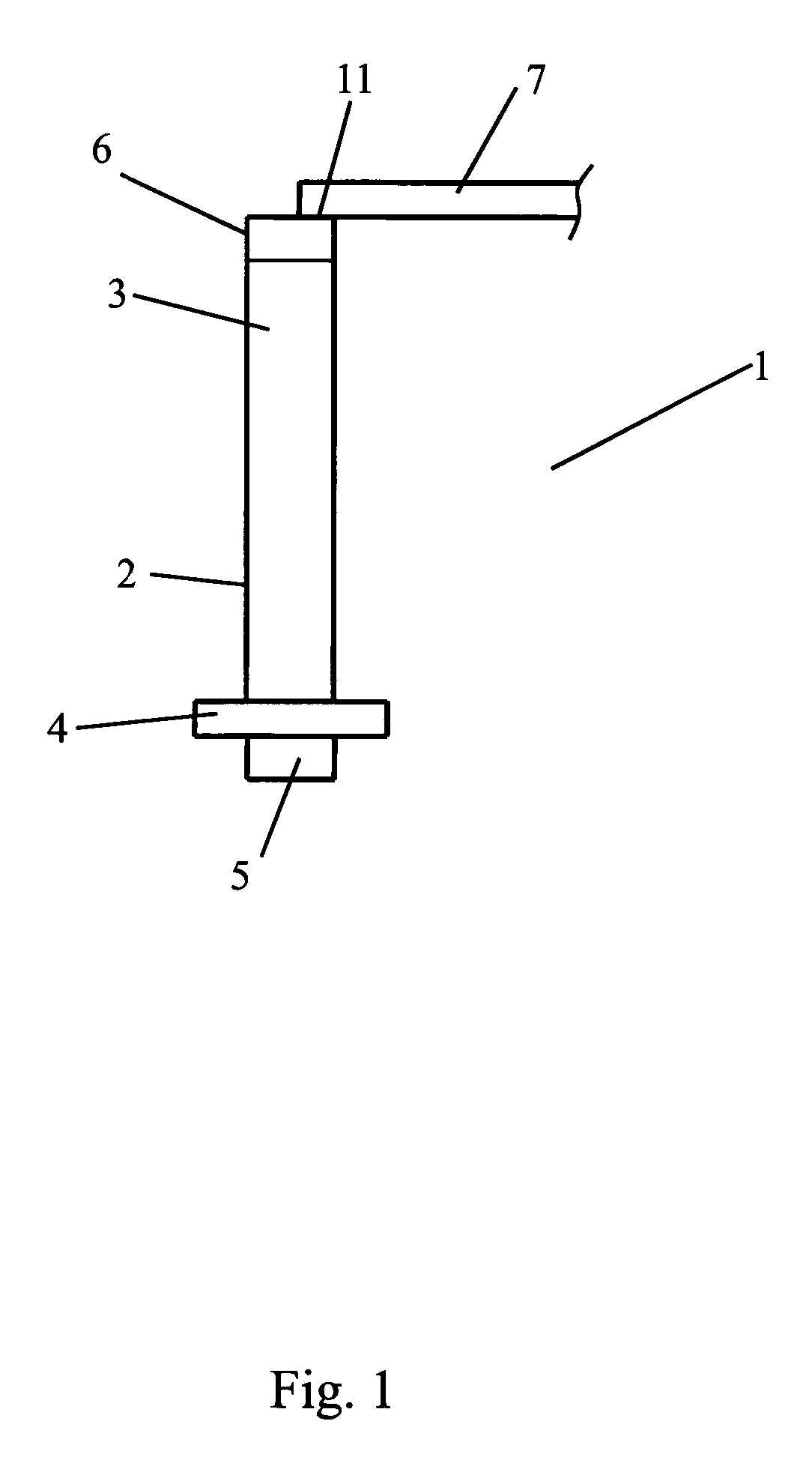
[0024]FIG. 1 shows a component of a gas turbine, in particular a jet turbine, in the form of a turbine blade or compressor blade 1, in which the present invention can be introduced. Blade 1 has a blade main body 2 with a blade portion 3 and a blade foot 5, which may comprise a molded part 4 for the form-fitting insertion of blade 1 into a disk. The present invention can be used both for rotating blades, which move during the operation of the turbine, as well as for stationary guide vanes. The present example of embodiment relates to a guide vane, which is disposed in stationary manner in the gas turbine.

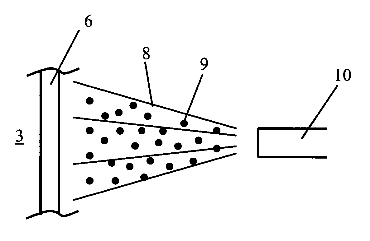
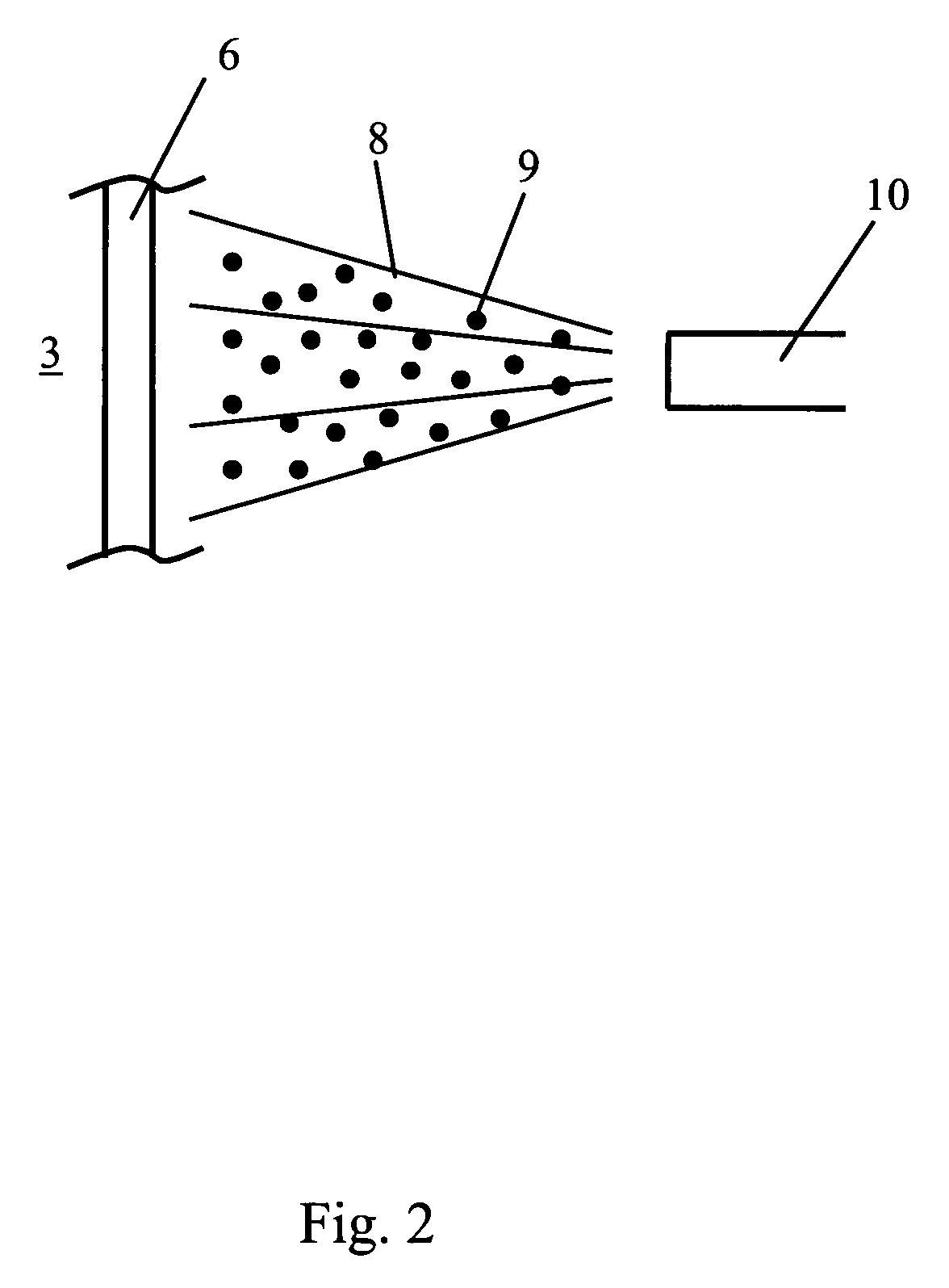
[0025]At the tip of the vane, a running-in layer 6 is provided, which is disposed so that it accurately fits with an adjacent component 7, such as, for example a shroud of an adjacent rotor.

[0026]In order to make possible an accurately fitting arrangement of blade 1 and the adjacent rotor component 7, the parts are designed so that they are in friction contact with one another at lea...


PUM

PropertyMeasurementUnit
sizeaaaaaaaaaa
particle velocityaaaaaaaaaa
pressureaaaaaaaaaa

Abstract

The present invention relates to a method for producing a component, in particular a blade for a gas turbine, wherein a main body (2) is provided, to which a running-in layer (6) is applied, which can be worn away at least partially during operation to form an accurately fitting surface (11), wherein the running-in layer is applied by kinetic cold-gas compacting, and a component, in particular a blade for a gas turbine, comprising a main body, to which a running-in layer is applied, which can be worn away at least partially during operation to form an accurately fitting surface, wherein the running-in layer is a porous layer made of a Ti alloy.

Description

BACKGROUND OF THE INVENTION[0001]1. Field of the Invention[0002]The present invention relates to a method for producing a component, in particular a blade for a gas turbine, which comprises a main body onto which a running-in layer is applied, which is worn away at least partially during operation to form an accurately fitting surface, as well as a corresponding component, in particular a compressor blade or turbine blade for a jet turbine.[0003]2. Prior Art[0004]In gas turbines and particularly jet turbines, different components that must be disposed relative to one another in a very accurate fit in order to assure a high efficiency of the engine and to avoid losses are utilized both in the compressor region as well as in the turbine region. For example, care must be taken that the blades used in the compressor region and in the turbine region optimally receive flow, so that losses of efficiency do not occur due to gaps and free spaces resulting from defective fitting. This applies...

Claims


Application Information

Patent Timeline
Patent Type & Authority Patents(United States)
IPC IPC(8): F01D5/28C23C24/04F01D11/12
CPCC23C24/04F01D5/288F01D11/122Y02T50/67Y02T50/60
Inventor JAKIMOV, ANDREASSCHNEIDERBANGER, STEFANHERTTER, MANUEL
Owner MTU AERO ENGINES GMBH
Why Eureka
Try Eureka