Expandable portable wall partition

a portable wall and expansion technology, applied in the field of adjustable partitions, can solve the problem of not allowing complete flexibility in the placement of wall units

Inactive Publication Date: 2009-10-08
VERSARE SOLUTIONS
View PDF7 Cites 24 Cited by
  • Summary
  • Abstract
  • Description
  • Claims
  • Application Information

AI Technical Summary

Benefits of technology

[0006]A principal object and advantage of the present invention is to provide an adjustable portable partition that can be manufactured in standard lengths but which can be expanded incrementally horizontally to a desired length.
[0007]Another principal object and advantage of the present invention is that the partition can be expanded to any length between the closed position and its maximum length without taking on a zig-zag or accordion shape.
[0008]Another principal object and advantage of the present invention is that it provides one or more non-sliding end members which stabilize the partition.
[0009]Another principal object and advantage of the present invention is that the non-sliding end members may be chosen from a set of different structures in various combinations.
[0010]Another principal object and advantage of the present invention is that the sliding connectors between panel members allow the bottom panels to be slid over an uneven surface, typically by wheels, while remaining upright.

Problems solved by technology

This method is relatively inexpensive and it permits the formation of areas with a wide variety of shapes, but the free standing wall units present storage and handling problems and do not allow complete flexibility in the placement of the wall units.

Method used


Image

  • Expandable portable wall partition
  • Expandable portable wall partition
  • Expandable portable wall partition

Examples


fifth embodiment

[0043]A fifth embodiment is shown in FIG. 10. Here, one of the non-sliding end members 18 is pivotally connected to one of the plurality of slidingly engaged panels 12 at a pivot point 19. While FIG. 11 shows that the member 18 is a full panel end member 20, the member 18 may instead be one of an inverted T-shaped member or an inverted U-shaped member.

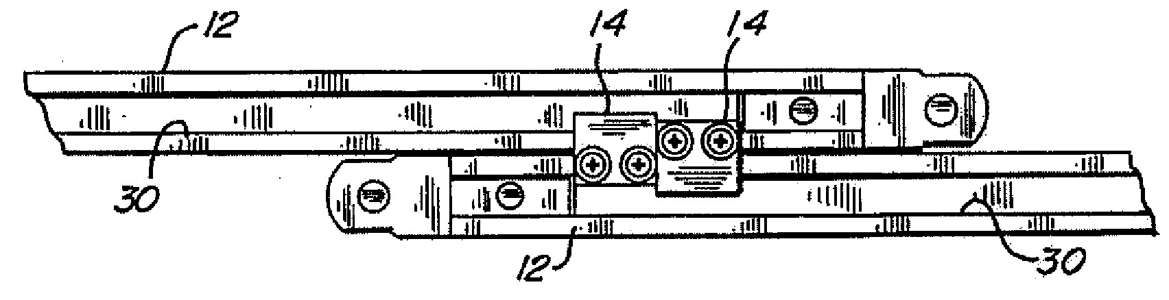
[0044]FIGS. 12a and 12b show one embodiment of a connector 14 that interconnects the plurality of upright, slidingly engaged panel members 12. In this embodiment each of the plurality of upright, slidingly engaged panel members 12 further comprises a horizontally extending top channel 30, with the top channel 30 of adjacent slidingly engaged panel members 12 interconnected by the connectors 14. As shown in FIG. 12b, the horizontally extending top channels 30 are preferably U-shaped and further comprise a horizontally extending base 32 and paired, opposing, horizontally extending flanges 34. The horizontally extending flanges 34 form a ...

second embodiment

[0046]FIGS. 13a and 13b illustrate the connectors 14. Here, the connectors 14 further comprise a first portion 42 fixedly attached to one of the panels 12, a transition portion 44 extending at an angle from the first portion 42, and a third portion 46 extending at an angle from the transition portion 44. The third portion 46 slidingly engages the top channel 30 of an adjacent panel 12. The third portion 46 further comprises an L-shaped portion 46a and a U-shaped portion 46b.

[0047]The partition 10 is fully opened when the third portions 46 of adjacent upright panel members 12 abut one another, thus preventing further slidable motion of the panel members 12.

sixth embodiment

[0048]the partition 10 is shown in FIGS. 14 and 15. In this embodiment the upright panel members, in addition to slidingly engage each other, are also nested.

[0049]It will be understood that only the top structure of the panels has been described, but that the same or equivalent structure may be on the bottom of the panels 12.

[0050]Turning to FIG. 16a, a front elevational view of any of the above embodiments shows the expandable, portable partition 10 resting on an even floor surface F. Three panels 12 are shown: panels 12c, 12d, and 12e. It will be seen that the height of the floor surface F rises between the left panel 12c and the middle panel 12d, and then flattens out again at panel 12f. Because the top connectors 14e and 14f and the bottom connectors 14g and 14h move independently, the bottom connectors 14c and 14d interconnecting the middle panel 12d to the outer panels 12c and 12e are separated by a length L1 that is greater than the separation L2 between corresponding top co...


PUM


Abstract

A horizontally expandable, portable wall partition is incrementally expandable between a closed position and an open position. The portable wall partition consists of a number of upright panel members that are sidewardly adjacent and vertically parallel to one another. These panel members are interconnected by connectors that allow the panels to slide past one another from the closed position to the expanaded position. The partition may also have non-sliding end members that provide stability to the partition. The partition may also have nested panels.

Description

BACKGROUND OF THE INVENTION[0001]The present invention relates generally to the field of adjustable partitions. In particular, the present invention addresses a portable wall partition that can be incrementally adjusted horizontally to a desired length, without being folded into an accordion or zig-zag configuration.[0002]Adjustable, portable partitions are known. See, e.g. U.S. Pat. Nos. 6,009,930 and 6,068,041; and U.S. Patent Publication No. 2002 / 0117270, all of which are hereby incorporated by reference.[0003]Such free standing wall units are used for dividing large areas into smaller private areas. This method is relatively inexpensive and it permits the formation of areas with a wide variety of shapes, but the free standing wall units present storage and handling problems and do not allow complete flexibility in the placement of the wall units.[0004]In particular, there is a need for an adjustable portable wall partition that can be manufactured in standard lengths but which c...

Claims


Application Information

Patent Timeline
Patent Type & Authority Applications(United States)
IPC IPC(8): E05D15/12E05D15/56E04H1/12
CPCE04B2/7425
Inventor RYAN, JEFFREY W.JANTSCHEK, ROBERT J.
Owner VERSARE SOLUTIONS
Why Eureka
Try Eureka