Hydraulically damped mounting device

a mounting device and hydrophilic technology, applied in the direction of shock absorbers, machine supports, mechanical equipment, etc., can solve the problems of limited space within the passageway partition, affecting the size of the opening, and affecting the characteristics of the moun

Inactive Publication Date: 2009-10-08
DTR VMS LTD
View PDF6 Cites 13 Cited by
  • Summary
  • Abstract
  • Description
  • Claims
  • Application Information

AI Technical Summary

Problems solved by technology

Furthermore, the surface of the diaphragm which is in contact with the fluid in the working chamber may be covered by a snubber plate, with openings therein for fluid communication therethrough between the upper surface of the diaphragm and the rest of the working chamber, and it has been found that the size of those openings also affects the characteristics of the mount.
One issue when producing a mount of the “cup and boss” type is to ensure that the characteristics of the passageway are appropriate.
Normally, the passageway is formed in a rigid partition separating the working and compensation chambers, and thus there is limited space available within that partition for the passageway.

Method used


Image

  • Hydraulically damped mounting device
  • Hydraulically damped mounting device
  • Hydraulically damped mounting device

Examples


first embodiment

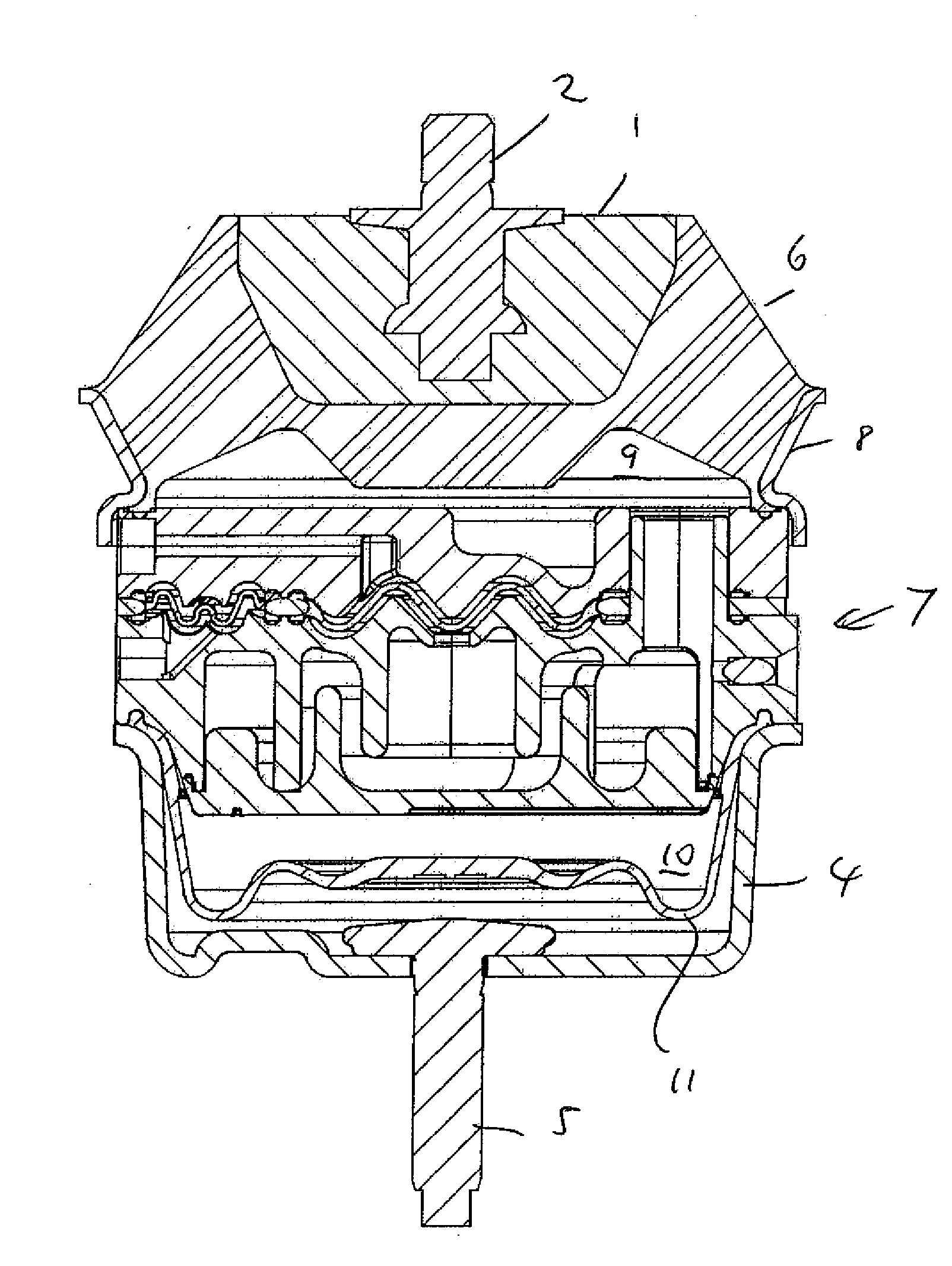
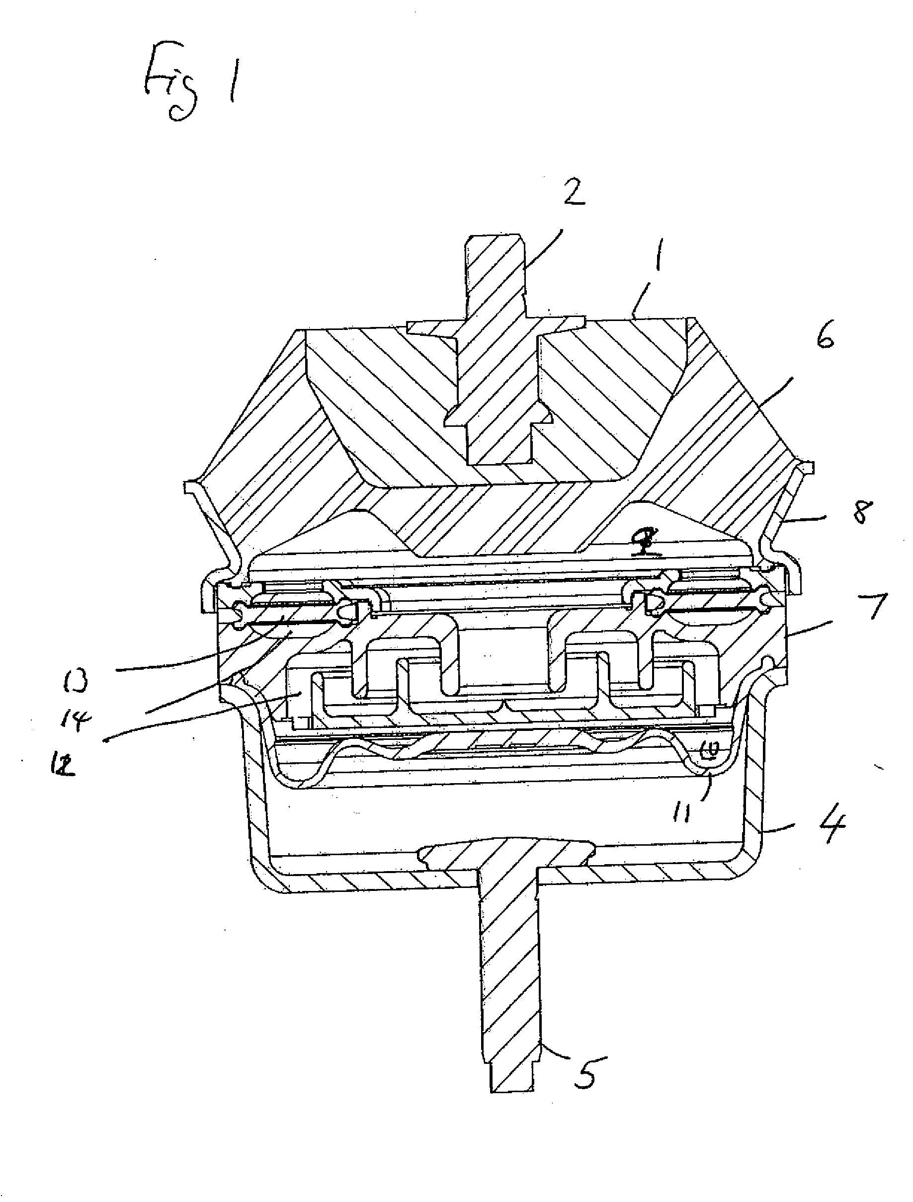
[0041]the present invention will now be described with reference to FIGS. 1 to 5.

[0042]Referring first to FIG. 1, a hydraulically damped mounting device being a first embodiment of the invention is shown for damping vibration between two parts of a structure (not shown). For example, the mounting device may be used to damp vibration between a vehicle engine and a chassis of the vehicle. The mount has a boss 1 connectable via a fixing bolt 2 to one of the parts of the structure, and the other part of the structure is connectable to a generally U-shaped cup 4 via a further fixing bolt 5. A resilient spring 6 of e.g. rubber interconnects the boss 1 and cup 4. A rigid partition 7 is mounted on the cup 4 to extend across its mouth, and a bracket 8 is mounted on the partition 7, so that the spring 6 is connected to the cup 4 via the bracket 8 and the partition 7.

[0043]A working chamber 9 is defined within the mounting device, bounded by the resilient spring 6 and the partition 7. Moreover...


PUM


Abstract

A hydraulically damped mounting device has two anchor parts connected by deformable wall. A partition is associated with one of the anchor parts and defines, together with the deformable wall a working chamber for hydraulic fluid. The working chamber is connected via a passageway to a compensation chamber partially bounded by another deformable wall. The partition separates the working and compensation chambers, and the device has a diaphragm being a barrier between the hydraulic fluid and a gas. In one arrangement at least part of the passageway is formed within a cavity in the partition in which there are projections which are arranged to overlap, and so define a convoluted path for the hydraulic fluid around the projections. In another arrangement a duct to a diaphragm part is at least partially formed by a cavity within the partition, which cavity has cylindrical projections arranged one within the other and overlapping to form a convoluted path for hydraulic fluid. In a third arrangement the passageway has a branch to the diaphragm, which branch is convoluted as it passages through a cavity in the partition containing cylindrical projections.

Description

CROSS-REFERENCE TO RELATED APPLICATIONS[0001]This application claims priority on British Application No. GB0806073.3, filed Apr. 3, 2008.BACKGROUND OF THE INVENTION[0002]1. Field of the Invention[0003]The present invention relates to a hydraulically damped mounting device. Such a device usually has a pair of chambers for hydraulic fluid, connected by suitable passageway, and damping is achieved due to the flow of fluid through that passageway.[0004]2. Summary of the Prior Art[0005]EP-A-0115417 and EP-A-0172700 discussed two different types of hydraulically damped mounting devices for damping vibration between two parts of a piece of machinery, e.g. a car engine and a chassis. EP-A-0115417 disclosed various “cup and boss” type of mounting devices, in which a “boss”, forming one anchor part to which one of the pieces of machinery was connected, was itself connected via a deformable (normally resilient) wall to the mouth of a “cup”, which was attached to the other piece of machinery an...

Claims


Application Information

Patent Timeline
Patent Type & Authority Applications(United States)
IPC IPC(8): F16F13/00
CPCF16F13/105F16F13/10
Inventor JONES, ALUNJOHNSON, RICHARD DAVID EDWARD
Owner DTR VMS LTD
Why Eureka
Try Eureka