Microparticle/aerosol-collecting device for office machine

a technology of microparticles and aerosols, which is applied in the direction of printing, other printing apparatus, etc., can solve the problems of misoperation of the printer, ink aerosols falling onto unexpected parts of the printer, affecting the printing quality, etc., and achieves the effect of ensuring printing quality and avoiding misoperation of the office machin

Inactive Publication Date: 2009-10-08
KINPO ELECTRONICS
View PDF5 Cites 27 Cited by
  • Summary
  • Abstract
  • Description
  • Claims
  • Application Information

AI Technical Summary

Benefits of technology

[0008]It is therefore a primary object of the present invention to provide a microparticle / aerosol-collecting device for office machine. The microparticle / aerosol-collecting device is positioned near a printing section or a printing head. The microparticle / aerosol-collecting device includes a housing having an internal space and an opening and includes an absorption section arranged in the space. The absorption section has multiple passages and is rotationally drivable by a motor. When driven by the motor, the absorption section creates a negative pressure effect to suck air into the absorption section, whereby the microparticles or ink aerosols suspended in the air are entrained by the air to go through the passage into the absorption section. A cleaning unit is arranged in the absorption section. After the microparticles or ink aerosols go into the absorption section, the microparticles or ink aerosols are absorbed and removed by the cleaning unit without attaching to any portion of the office machine. Therefore, the printing quality can be ensured and misoperation of the office machine can be avoided.

Problems solved by technology

This will affect the printing quality.
These ink aerosols will eventually fall onto unexpected portions of the printer, for example, the transmission members of the printer.
This will affect the judgment of the jet carrier control system to cause misoperation of the printer.
For example, the device can only absorb powders and dusts from one face of the paper, while failing to absorb the powders and dusts attaching to the other face of the paper.
Furthermore, all the above devices cannot collect or clean off the ink aerosols or microparticles suspended in the air.

Method used


Image

  • Microparticle/aerosol-collecting device for office machine
  • Microparticle/aerosol-collecting device for office machine
  • Microparticle/aerosol-collecting device for office machine

Examples


second embodiment

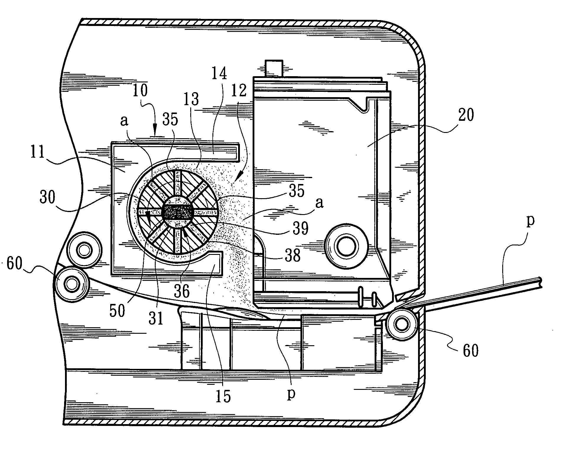
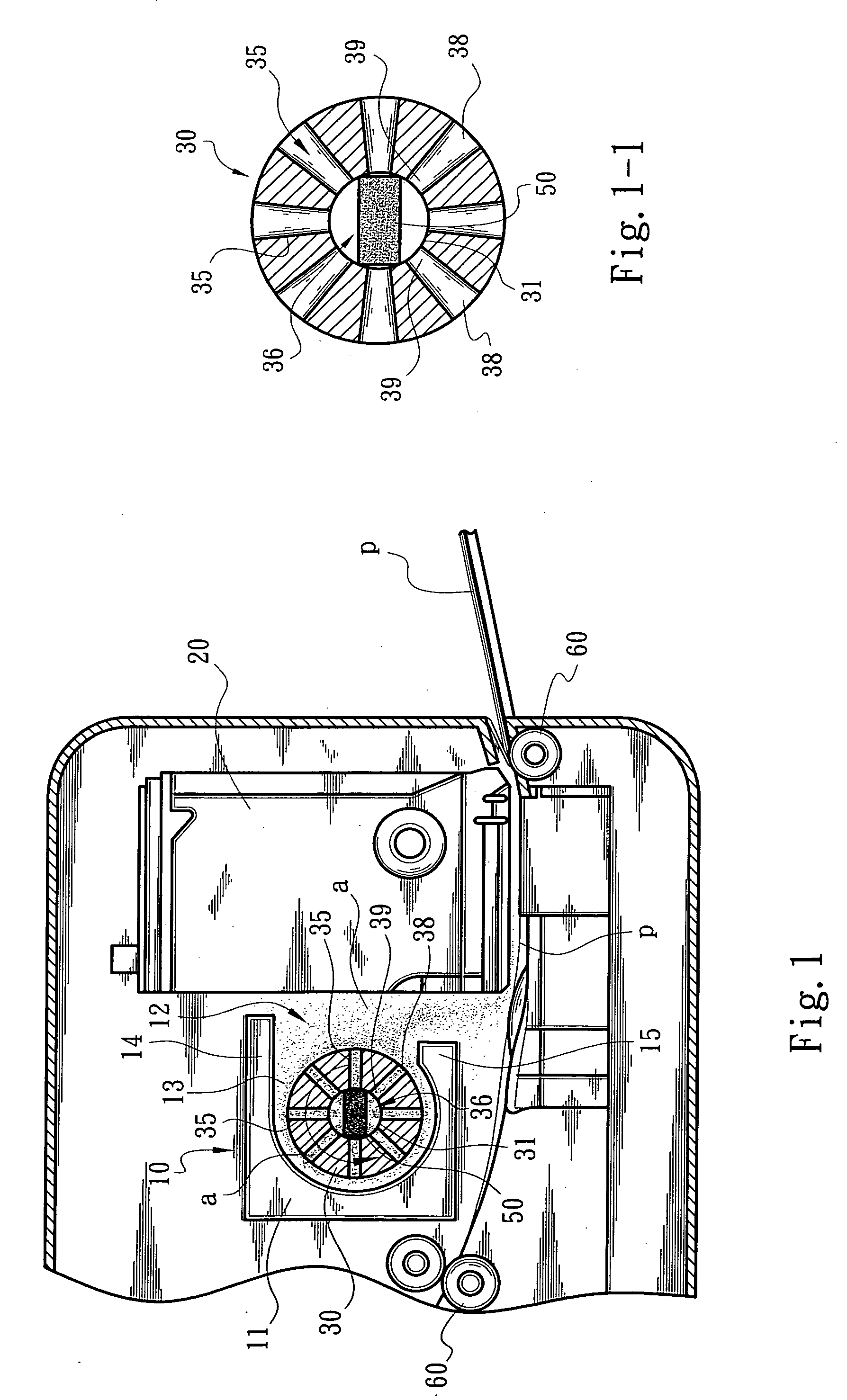
[0026]FIG. 3 shows the microparticle / aerosol-collecting device 10 for office machine of the present invention. The absorption section 30 is formed with multiple radial curved passages 37 each having an inlet 38 and an outlet 39. The passages 37 communicate with the chamber 36 of the shaft 31. According to a cross-section of the absorption section 30, the passages 35 are radially arranged in a turbination-like pattern. The cleaning unit 50 is positioned in the chamber 36 of the shaft 31. When a paper p is fed by rollers 60 to pass through a printing section or printing head 20 for printing operation, the absorption section 30 is rotated by the motor 40 to suck in the microparticles or ink aerosols a generated in the printing operation. The microparticles or ink aerosols a go through the passages 37 into the chamber 36 and then are absorbed by the cleaning unit 50.

[0027]The curvature of the passages 37 is changeable. For example, the curvature of the passage 37 can be such increased t...

third embodiment

[0028]FIG. 4 shows the microparticle / aerosol-collecting device 10 for office machine of the present invention, in which the absorption section 30 is positioned in the housing 11 to carry static for absorbing or collecting microparticles or ink aerosols a suspended in the air. The absorption section 30 has a form of a roller. The absorption section 30 is preferably made of plastic, rubber or chemical fiber material. The absorption section 30 is rotationally drivable by the motor 40 to abrade air and create static.

[0029]As shown in FIG. 4, a cleaning unit 50 is arranged in the space 13 between the housing 11 and the absorption section 30 in contact with a surface 33 thereof. When the absorption section 30 rotates, the cleaning unit 50 wipes off the microparticles or ink aerosols a from the surface 33 of the absorption section 30.

[0030]When a paper p is fed by rollers 60 to pass through a printing section or printing head 20 for printing operation, the microparticles or ink aerosols a ...


PUM


Abstract

A microparticle / aerosol-collecting device for office machine. The microparticle / aerosol-collecting device is positioned near a printing section or a printer head. The microparticle / aerosol-collecting device includes a housing having an upper section and a lower section defining a space. The space has an opening. An absorption section is arranged in the space. The absorption section is formed with a chamber and multiple passages communicating with the chamber. The microparticle / aerosol-collecting device further includes a cleaning unit disposed in the chamber of the absorption section. The absorption section is rotationally drivable by a motor to create a negative pressure effect around the absorption section, whereby the airflow is collectively taken into the chamber of the absorption section through the passages thereof. Accordingly, the microparticles or ink aerosols are entrained by the airflow to go into the chamber. The microparticles or ink aerosols are then absorbed and removed by the cleaning unit.

Description

BACKGROUND OF THE INVENTION[0001]The present invention is related to a microparticle / aerosol-collecting device, and more particularly to a rotational microparticle / aerosol-collecting device mounted in an office machine for collecting ink aerosols suspended in the air.[0002]A conventional printer includes a printing head positioned above a paper-feeding path by a set height. The printing head is reciprocally movable in a direction normal to the paper-feeding path, whereby the printing head is able to jet ink onto a paper and print the paper with figures or characters.[0003]In general, the printing head includes multiple jet nozzles for jetting ink onto a paper. In the jetting operation, some ink drops often stagnate around the jet nozzles to eventually form solid sediments. The sediments will partially clog the jet nozzles to change the jet direction. This will affect the printing quality. Moreover, in printing operation, some ink aerosols are spread and suspended in the air. These i...

Claims


Application Information

Patent Timeline
Patent Type & Authority Applications(United States)
IPC IPC(8): B41J2/165
CPCB41J29/13B41J29/38B41J29/377
Inventor LAI, YI-LINPAN, TIEN-YUCHEN, TUO-JEN
Owner KINPO ELECTRONICS
Why Eureka
Try Eureka