Automated Temperature Contrast and Dynamic Pressure Modules for a Hot or Cold Wrap Therapy System

a technology of dynamic pressure and temperature contrast, which is applied in the direction of therapeutic heating, contraceptive devices, therapeutic cooling, etc., can solve the problems of skin and tissue damage, burns or other damage to the recipient, and the loss of the opportunity to receive therapy, so as to increase the cost and bulk

Inactive Publication Date: 2009-10-08
VITALWEAR
View PDF1 Cites 45 Cited by
  • Summary
  • Abstract
  • Description
  • Claims
  • Application Information

AI Technical Summary

Benefits of technology

[0009]To achieve the foregoing and in accordance with the present invention, a replaceable module for use with a thermal contrast therapy systems and methods for module functionality are provided. Such systems are useful for providing effective pressure and contrast thermal therapy without the increased costs and bulk associated with such a system.

Problems solved by technology

If cold treatments are too cold, they may cause skin and tissue damage.
Similarly, if hot treatments are too hot, they may burn or otherwise damage the recipient.
If it is difficult for a therapy recipient to self apply a therapy, the opportunity to receive therapy may be diminished.
Furthermore, if therapies are complicated and / or uncomfortable, a therapy recipient is less likely to undergo the therapy, although it may be beneficial.
Typically, contrast therapy systems designed to provide pressure therapy, and manual and automatic contrast therapy are very cumbersome due to the required sizing and weight of the unit.
Additionally, with the increase in features incorporated in current contrast therapy systems, there is an analogous increase in manufacturing and consumer costs.
Both increased costs and bulk easily deter a potential user from engaging in contrast or pressure therapy.
No such replaceable modules for contrast therapy units currently exist.

Method used


Image

  • Automated Temperature Contrast and Dynamic Pressure Modules for a Hot or Cold Wrap Therapy System
  • Automated Temperature Contrast and Dynamic Pressure Modules for a Hot or Cold Wrap Therapy System
  • Automated Temperature Contrast and Dynamic Pressure Modules for a Hot or Cold Wrap Therapy System

Examples


Embodiment Construction

[0052]The present invention will now be described in detail with reference to several embodiments thereof as illustrated in the accompanying drawings. In the following description, numerous specific details are set forth in order to provide a thorough understanding of the present invention. It will be apparent, however, to one skilled in the art, that the present invention may be practiced without some or all of these specific details. In other instances, well known process steps and / or structures have not been described in detail in order to not unnecessarily obscure the present invention. The features and advantages of the present invention may be better understood with reference to the drawings and discussions that follow.

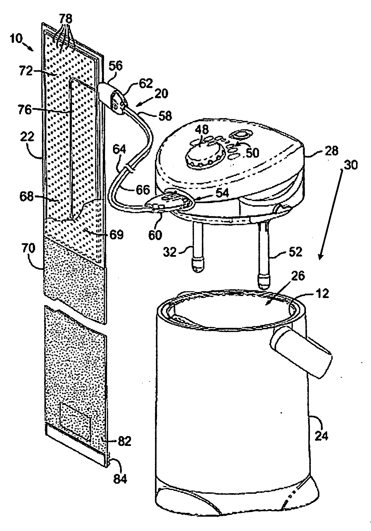
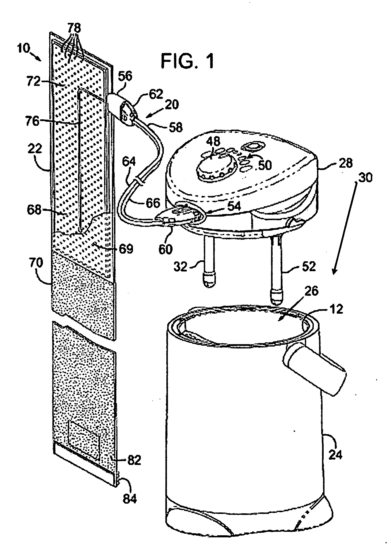
[0053]The present invention relates to removable modules for use in a contrast therapy system. The removable modules enable a rapid transformation of a contrast therapy system to include a pressure system or automated contrast therapy. This transformative proper...


PUM


Abstract

The present invention relates to a replaceable module for use with a thermal contrast therapy systems. The replaceable module may be an automated thermal contrast therapy module which includes a casing, a manual mixing valve, an automated mixing valve, an automated mixing valve actuator, a temperature sensor, and an interface. A cold and a hot fluid are mixed to generate a therapy fluid. The therapy fluid may be output to a therapy bladder. The second replaceable module is a compression therapy module which includes a casing, an air pump, a pneumatic solenoid, and a pressure monitor. The casing may include a pressurized air pathway including an air outlet. The pump may pressurize the air within the pathway, and the solenoid may regulate the air pressure using feedback from the pressure sensor. Additionally, a pressure relief valve may release pressure if it gets above a safety threshold. The compression therapy module may also include a fluid pathway.

Description

CROSS REFERENCE TO RELATED APPLICATIONS[0001]This is a continuation-in-part of co-pending U.S. application Ser. No. 10 / 267,247 filed on Oct. 8, 2002, entitled “Contrast Therapy System and Method”, now U.S. Pat. No. 7,211,104, which is hereby fully incorporated by reference.BACKGROUND OF THE INVENTION[0002]The present invention relates to a removable module for use in a contrast therapy system. The removable module enables a rapid transformation of a contrast therapy system to include a dynamic pressure system or automated contrast therapy. This transformative property enables reduced costs for a wide range of features to be included in a single lightweight contrast therapy system. The pressure module enables application of compression, massage and pulsation therapy to a therapy site. The automated contrast therapy module enables a programmable and automated temperature or contrast therapy.[0003]Numerous thermal therapy devices that apply external treatments to the body are known in ...

Claims


Application Information

Patent Timeline
Patent Type & Authority Applications(United States)
IPC IPC(8): A61F7/02
CPCA61F7/0085A61F7/02A61F2007/0295A61F2007/0056A61F2007/0054
Inventor SHAWVER, MICHAELEDELMAN, HOWARD
Owner VITALWEAR
Why Eureka
Try Eureka