Spring member for use in a microelectromechanical systems sensor

a microelectromechanical system and spring member technology, applied in the field of spring member for suspension of movable elements of mems sensors, can solve the problems of reducing the vertical stiffness

Active Publication Date: 2009-10-15
NXP USA INC
View PDF13 Cites 31 Cited by
  • Summary
  • Abstract
  • Description
  • Claims
  • Application Information

AI Technical Summary

Problems solved by technology

Unfortunately, folded spring members 30 are subject to twisting under high vertical loads such as mechanical shock in excess of, for example, 10 g, which can occur during testing and in use.
Indeed, failures have occurred under such high vertical loads.
This twisting effectively reduces the vertical stiffness and can result

Method used


Image

  • Spring member for use in a microelectromechanical systems sensor
  • Spring member for use in a microelectromechanical systems sensor
  • Spring member for use in a microelectromechanical systems sensor

Examples


Embodiment Construction

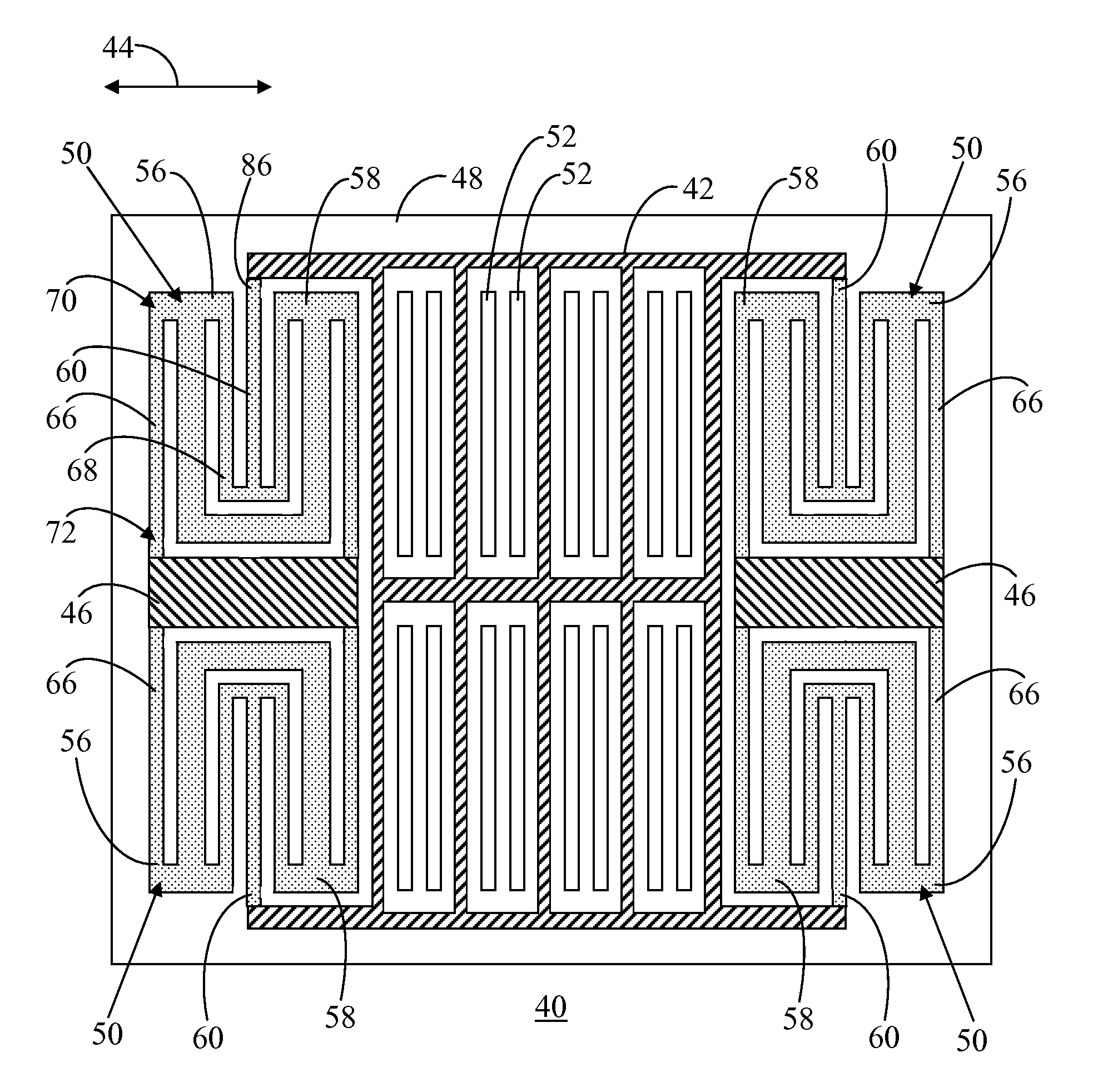
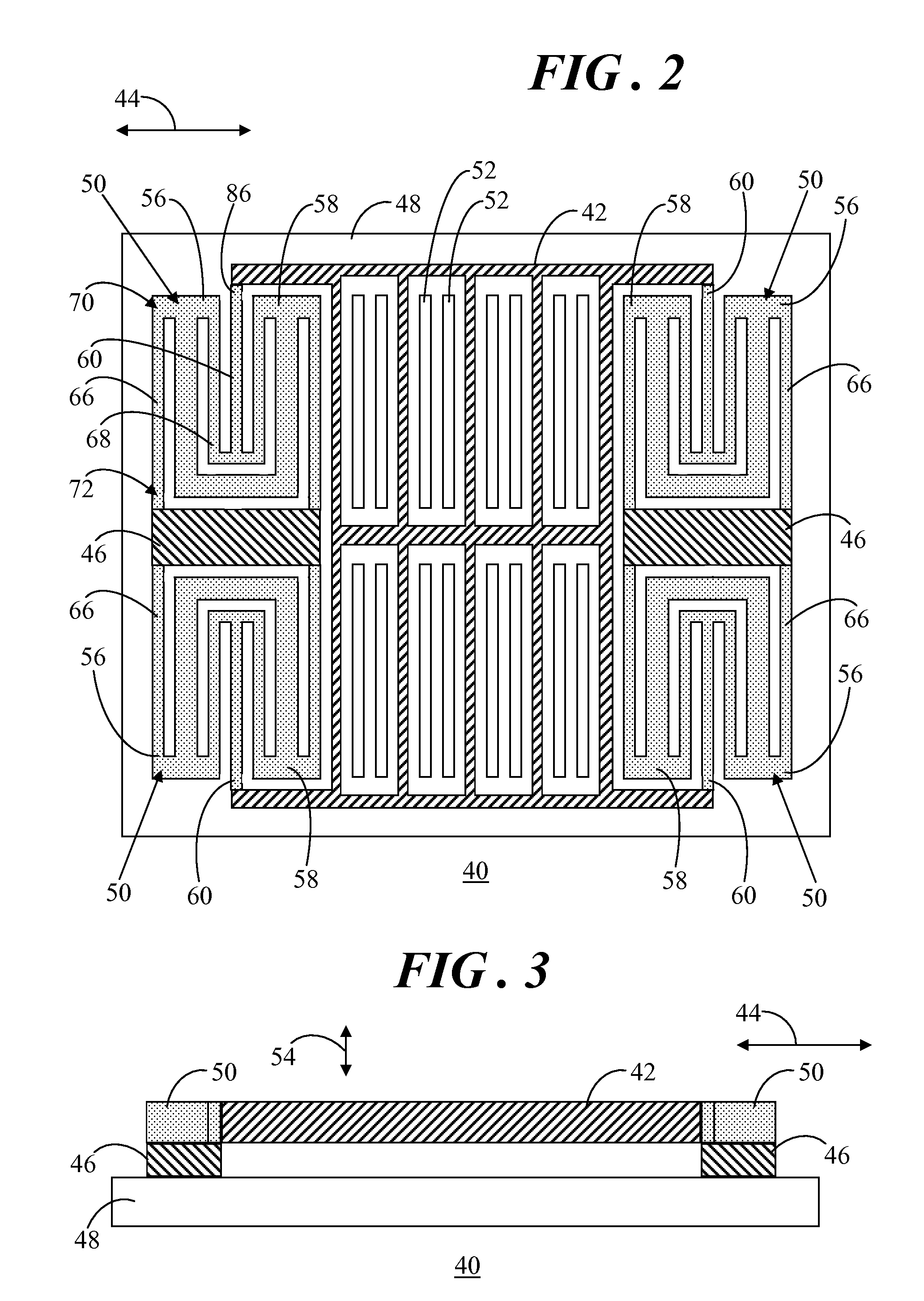
[0015]Referring to FIGS. 2-3, FIG. 2 shows a top view of a microelectromechanical (MEMS) sensor 40 in accordance with an embodiment of the invention, and FIG. 3 shows a side view of MEMS sensor 40. MEMS sensor 40 includes a movable element 42, distinguished in FIGS. 2 and 3 by upwardly and rightwardly directed hatching. Movable element 42 is adapted for motion in a lateral direction 44. Anchors 46, distinguished in FIGS. 2 and 3 by downwardly and rightwardly directed hatching, are coupled to an underlying substrate 48. MEMS sensor 40 further includes spring members 50, distinguished in FIGS. 2 and 3 by a dot pattern. Spring members 50 are interconnected between anchors 46 and movable element 42. Anchors 46 and spring members 50 function to suspend movable element 42 above substrate 48, as particularly illustrated in FIG. 3. Movement of movable element 42 in lateral direction 44 may be detected by sense electrodes 52 proximate movable element 42.

[0016]In this embodiment, spring membe...


PUM


Abstract

A device (96) includes a microelectromechanical (MEMS) sensor (40). The sensor (40) includes a movable element (42) adapted for motion in a direction (44) and an anchor (46) coupled to a substrate (48). The MEMS sensor (40) further includes spring members (50) interconnected between the movable element (42) and the anchor (46). Each of the spring members (50) includes beams (56, 58, 60) arranged in substantially parallel alignment, with the beam (60) positioned between the other beams (56, 58). Each of the beams (56, 58) is coupled to the anchor (46) and the beam (60) is coupled to the movable element (42). Each of the spring members (50) further includes a support structure (64) joined with the beams (56, 58) to provide vertical stiffness to the beams (56, 58) of the spring member (50).

Description

TECHNICAL FIELD OF THE INVENTION[0001]The present invention relates generally to microelectromechanical systems (MEMS) sensors. More specifically, the present invention relates to a spring member for suspension of a movable element of a MEMS sensor.BACKGROUND OF THE INVENTION[0002]Many devices and systems include a number of different types of sensors that perform various monitoring and / or control functions. Advancements in micromachining and other microfabrication processes have led to the manufacturing of a wide variety of microelectromechanical systems (MEMS) sensors to perform these monitoring and / or control functions.[0003]A MEMS sensor may be formed on a wafer that includes a substrate (also known as a handle layer), an insulating sacrificial layer of, for example, an oxide, overlying the substrate, and an active layer overlying the insulating layer. In general, a MEMS sensor typically includes a movable element, sometimes referred to as a proof mass, formed in the active laye...

Claims


Application Information

Patent Timeline
IPC IPC(8): F16F1/18
CPCG01P2015/0814G01P15/125
Inventor GEISBERGER, AARON A.
Owner NXP USA INC
Why Eureka
Try Eureka