

Pressure sensor
a pressure sensor and sensor technology, applied in the field of pressure sensors, can solve the problems of pressure sensor size increase, size and weight increase correspondingly,
- Summary
- Abstract
- Description
- Claims
- Application Information
AI Technical Summary
Problems solved by technology
Method used
Image

Examples
first embodiment
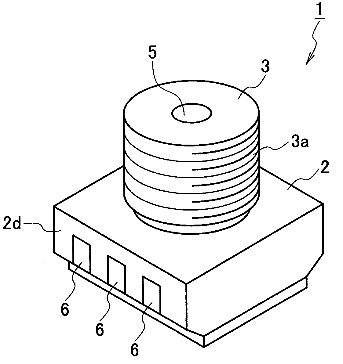
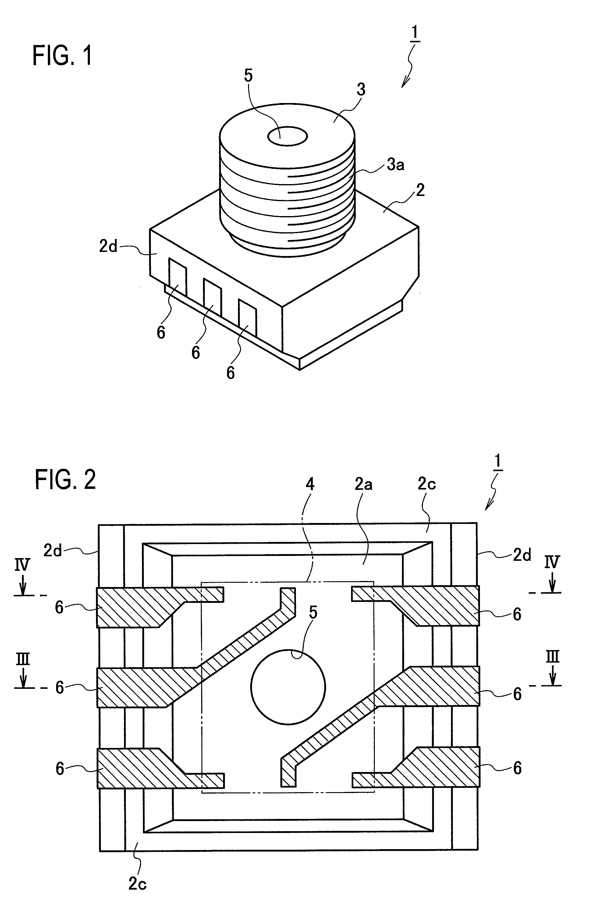
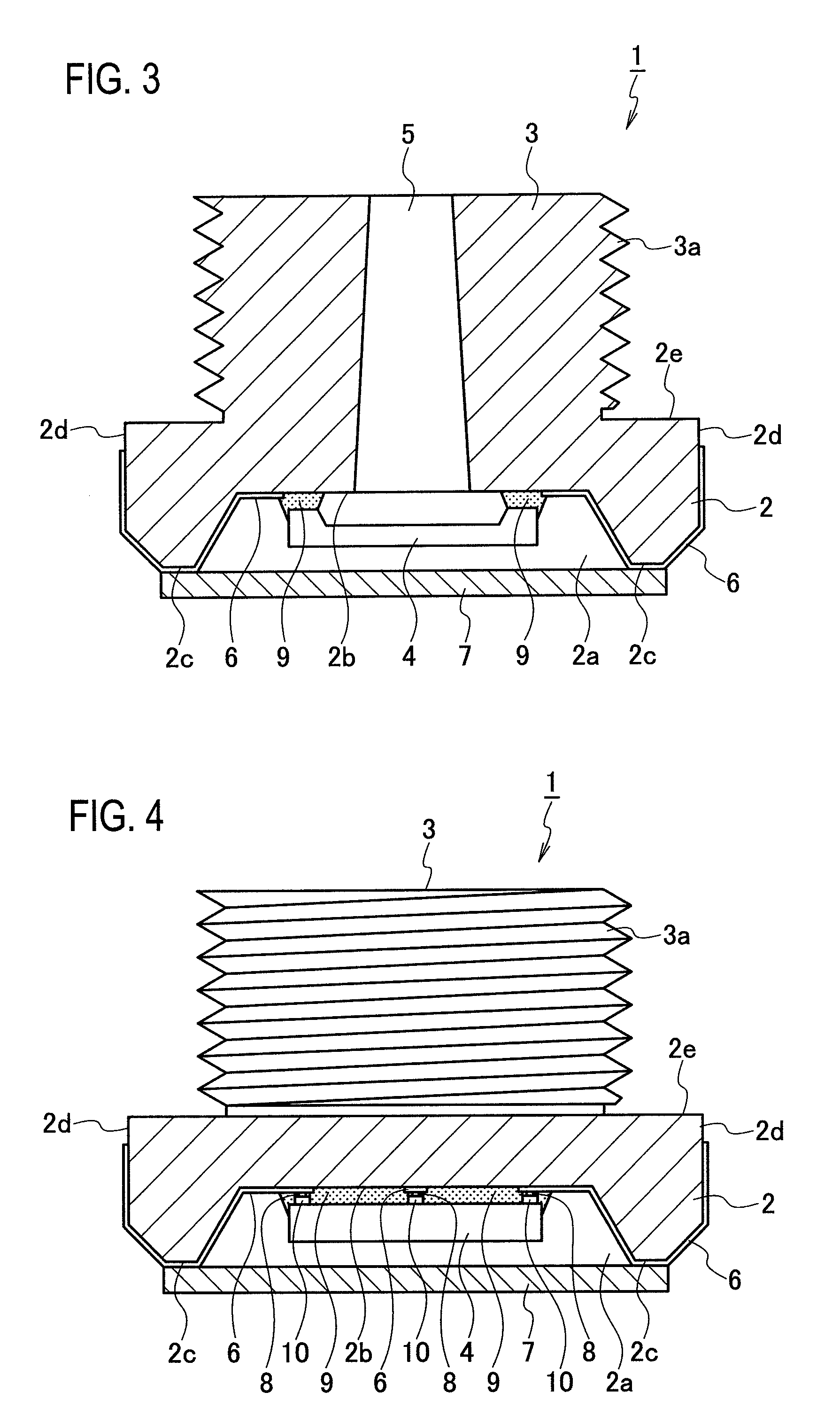
[0042]FIG. 1 is a perspective view of a pressure sensor according to a first embodiment of the present invention, FIG. 2 is a plan view of a pressure sensor as viewed from its back side (opposite side from a detection side by a pressure detecting element), FIG. 3 is a sectional view taken along the line III-III in FIG. 2, FIG. 4 is a sectional view taken along the line IV-IV in FIG. 2, FIG. 5 is a plan view of the pressure sensor as viewed from its back side and showing a sealing region of the pressure detecting element by a sealing agent, and FIG. 6 is a side view showing a state where the pressure sensor is mounted.
[0043]A pressure sensor 1 according to the present embodiment includes a substantially-cylindrical protrusion 3 provided on a flat surface (seal surface) 2e of a base portion 2 having a substantially rectangular parallelepiped appearance. In the present embodiment, the base portion 2 and the protrusion 3 correspond to a body portion.
[0044]The body portion (the base port...
second embodiment
[0062]FIG. 7 is a vertical sectional view of a pressure sensor according to a second embodiment of the present invention (corresponding to the sectional view of FIG. 3). A pressure sensor 1A according to the present embodiment includes same constituent elements as those of the pressure sensor 1 according to the first embodiment. Therefore, same constituent elements are denoted by common reference numerals, and redundant explanations thereof will be omitted.
[0063]In the present embodiment, a stepped recess 2a having the bottom face 2b and a step face 2f formed substantially at a central portion in a depth direction of a stepped recess 2a is formed on the base portion 2A. The pressure detecting element 4 is mounted on the bottom face 2b, and another element that is different from the pressure detecting element 4 (i.e., an element including a circuit that processes (i.e., filters, corrects, calculates, temperature compensates) a signal output from the pressure detecting element 4) is m...
third embodiment
[0068]FIG. 8 is a vertical sectional view of a pressure sensor according to a third embodiment of the present invention (sectional view corresponding to FIG. 3). A pressure sensor 1B according to the present embodiment has same constituent elements as those of the pressure sensor 1 or 1A of the first or second embodiment Therefore, the same constituent elements are denoted by common reference numerals, and redundant explanations thereof will be omitted.
[0069]In the present embodiment, an annular flange portion 13 protruding from an inner peripheral surface of the through hole 5 of a base portion 2B toward a center of the through hole 5 is formed. The pressure detecting element 4 is mounted on a surface 5a of the flange portion 13 on the side of a pressure introducing opening 5b of the through hole 5 by flip-chip bonding. Another element 4B that is different from the pressure detecting element 4 (i.e., an element including a circuit that processes (i.e., filters, corrects, calculates...
PUM
 Abstract
Description
Claims
Application Information