
Torsional resonance prevention

a torsional resonance and prevention technology, applied in the field of drilling, can solve the problems of rotational vibration, further boring into the medium, and medium to be either sheared or otherwise removed from the cavity

Active Publication Date: 2009-10-29
SCHLUMBERGER TECH CORP
View PDF4 Cites 15 Cited by
  • Summary
  • Abstract
  • Description
  • Claims
  • Application Information

AI Technical Summary

Benefits of technology

The present invention provides a system for drilling a cavity in a medium that includes a drill bit, a drillstring, a processor, and a controller. The system can determine the speed of the drill bit during operation and apply a force to the drill bit based on the determined speed. This allows for a more efficient and effective drilling process. The technical effect of the invention is to improve the speed and accuracy of drilling a cavity in a medium.

Problems solved by technology

When drilling in hard mediums, for example earthen formations, a common problem is rotational vibration caused by a “stick-slip” condition.
Stick-slip occurs when the drill bit either “bites” too much or too little of the medium to cause further boring into the medium.
When the drill bit bites too much of the medium, each of the cutters on the drill bit is engaging too much medium without enough torque to cause the medium to either be sheared or otherwise removed from the cavity.
Both stick and slip occurrences will cause torsional vibrations in the drillstring connecting the drill bit to the drill's rotational power source.
Furthermore, such torsional vibrations can reduce the life of the drill bit and associated drilling equipment, such as for example the rotational power source.
While the properties of the medium may at least partially affect the likelihood of stick-slip occurring, the properties of the medium may not be controllable, especially in earthen drilling operations.

Method used


Image

  • Torsional resonance prevention
  • Torsional resonance prevention
  • Torsional resonance prevention

Examples


Embodiment Construction

[0013]The ensuing description provides exemplary embodiments only, and is not intended to limit the scope, applicability or configuration of the disclosure. Rather, the ensuing description of the exemplary embodiments will provide those skilled in the art with an enabling description for implementing one or more exemplary embodiments. It being understood that various changes may be made in the function and arrangement of elements without departing from the spirit and scope of the invention as set forth in the appended claims.

[0014]Specific details are given in the following description to provide a thorough understanding of the embodiments. However, it will be understood by one of ordinary skill in the art that the embodiments may be practiced without these specific details. For example, circuits, systems, networks, processes, and other elements in the invention may be shown as components in block diagram form in order not to obscure the embodiments in unnecessary detail. In other i...


PUM


Abstract

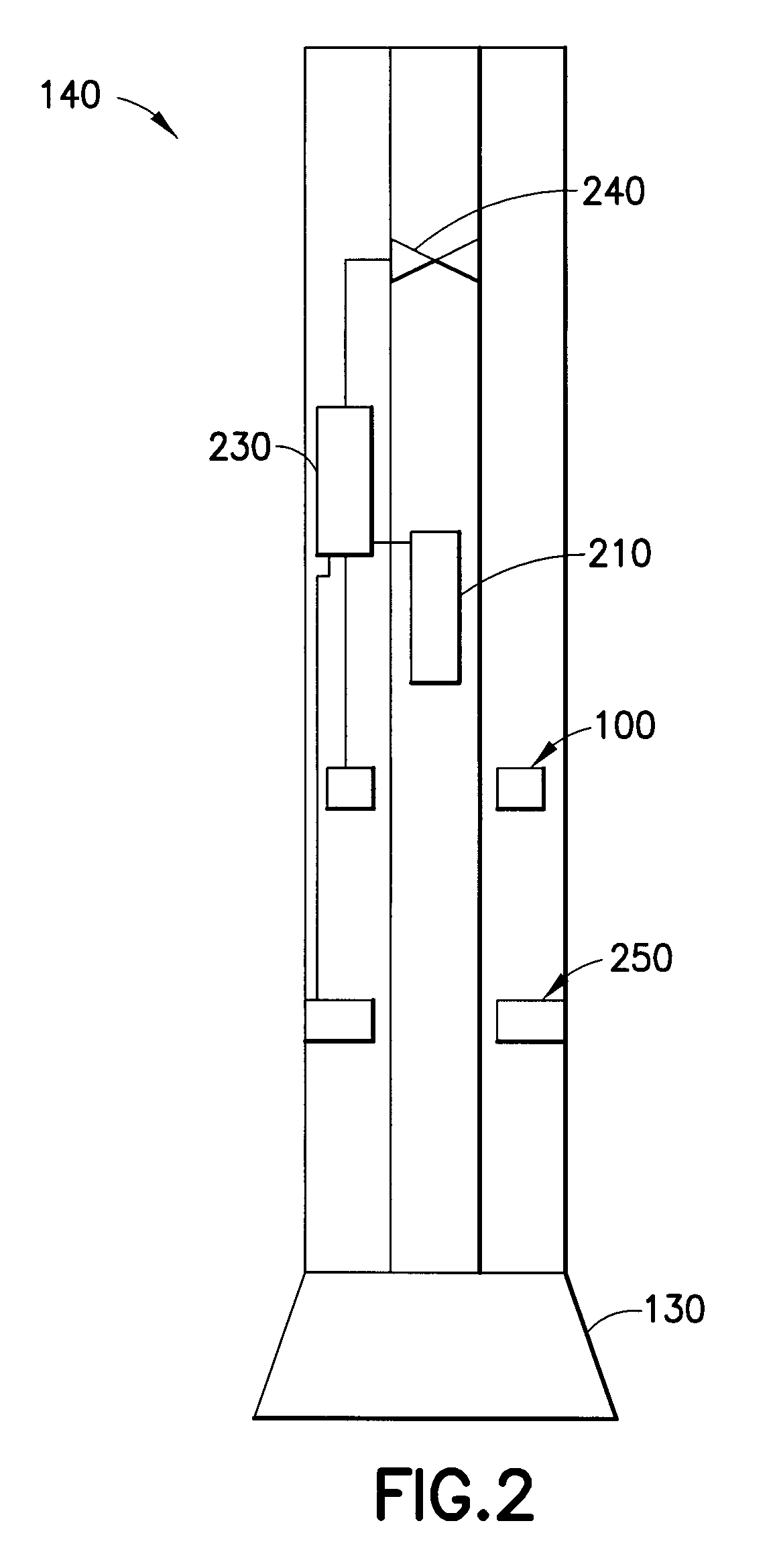
According to the invention, a system for drilling a cavity in a medium is disclosed. The system may include a drill bit, a processor, and a controller. The drill bit may be configured to rotate in the medium and remove at least a portion of the medium. The processor may be configured to receive a first set of data representative of a variable rotational speed of the drill bit during a length of time in the medium, and determine, based at least in part on the first set of data, a first resonant frequency of the variable rotational speed of the drill bit. The controller may be configured to receive a second set of data representative of the first resonant frequency of the variable rotational speed of the drill bit, and vary the force applied to the drill bit based at least in part on the second set of data.

Description

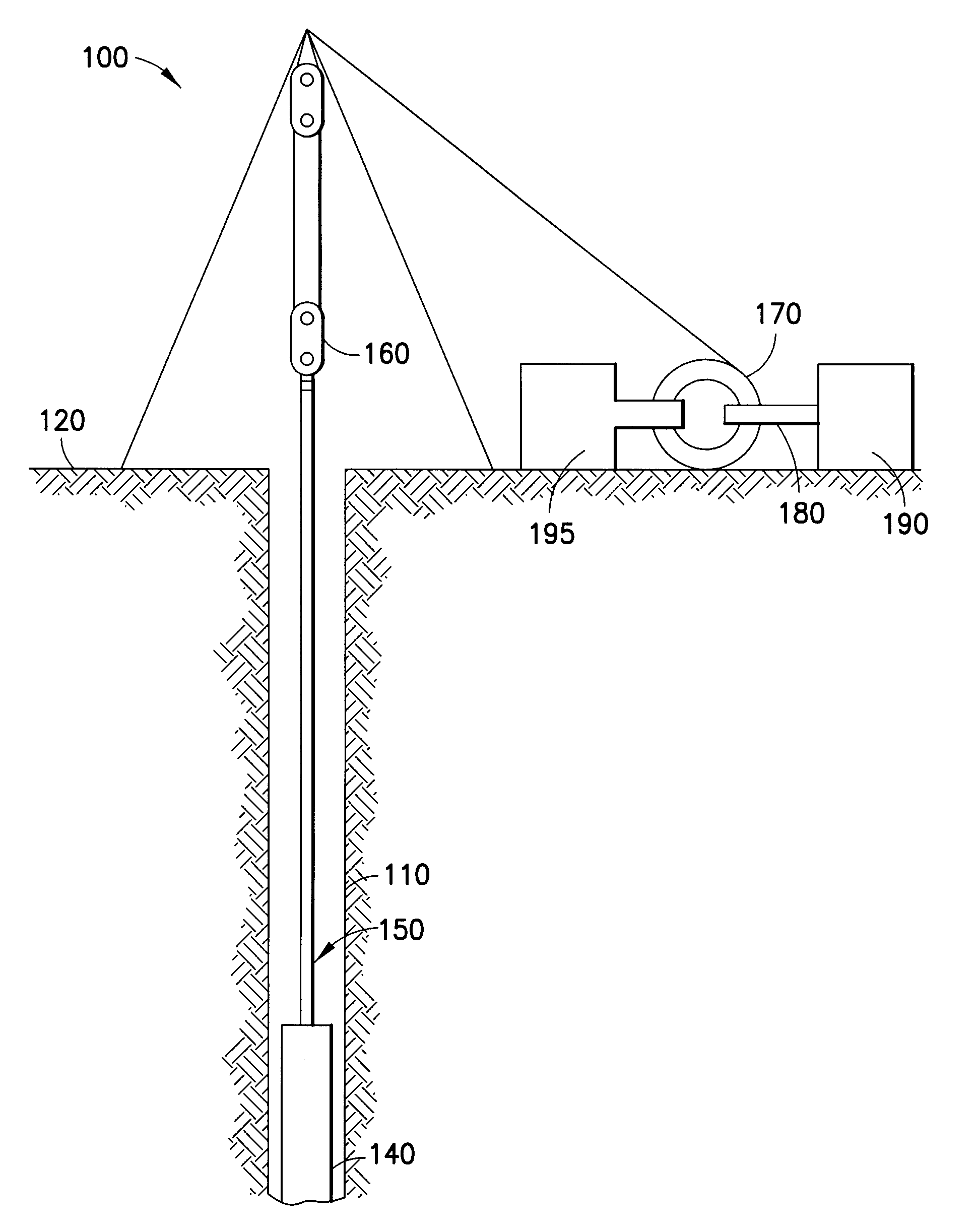
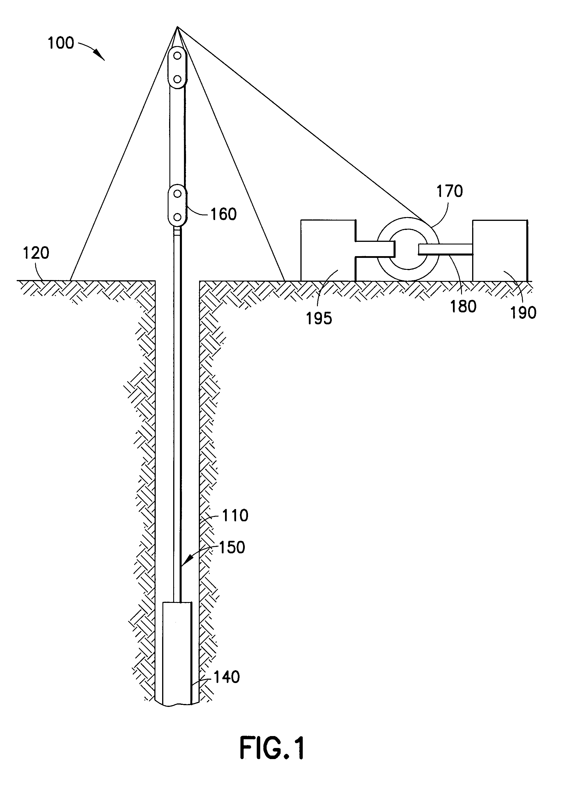
BACKGROUND OF THE INVENTION[0001]This invention relates generally to drilling. More specifically the invention relates to drilling in earthen formations.[0002]When drilling in hard mediums, for example earthen formations, a common problem is rotational vibration caused by a “stick-slip” condition. Stick-slip occurs when the drill bit either “bites” too much or too little of the medium to cause further boring into the medium. When the drill bit bites too much of the medium, each of the cutters on the drill bit is engaging too much medium without enough torque to cause the medium to either be sheared or otherwise removed from the cavity. When the drill bit bites too little of the medium, the path of least resistance for the drill bits may be to skip over the medium rather than remove material from the cavity. Both stick and slip occurrences will cause torsional vibrations in the drillstring connecting the drill bit to the drill's rotational power source.[0003]Torsional vibrations can ...

Claims


Application Information

Patent Timeline
Patent Type & Authority Applications(United States)
IPC IPC(8): E21B44/00E21B44/02
CPCE21B44/04E21B7/00E21B44/02
Inventor JEFFRYES, BENJAMIN
Owner SCHLUMBERGER TECH CORP
Learn More