Operation of Dual Gas Turbine Fuel System

a fuel system and gas turbine technology, applied in the direction of engine ignition, engine starter, turbine/propulsion engine, etc., can solve the problems of high hydrogen, difficult to operate a modern gas turbine on a normal, high-energy fuel, and complicated design of such a “dual gas” fuel system

Active Publication Date: 2009-11-05
GENERAL ELECTRIC CO
View PDF5 Cites 35 Cited by
  • Summary
  • Abstract
  • Description
  • Claims
  • Application Information

AI Technical Summary

Problems solved by technology

In general, it may be difficult to operate a modern gas turbine on a normal, high-energy fuel (for example, natural gas) and a high hydrogen, low energy fuel (for example, syngas)

Method used


Image

  • Operation of Dual Gas Turbine Fuel System
  • Operation of Dual Gas Turbine Fuel System

Examples


Embodiment Construction

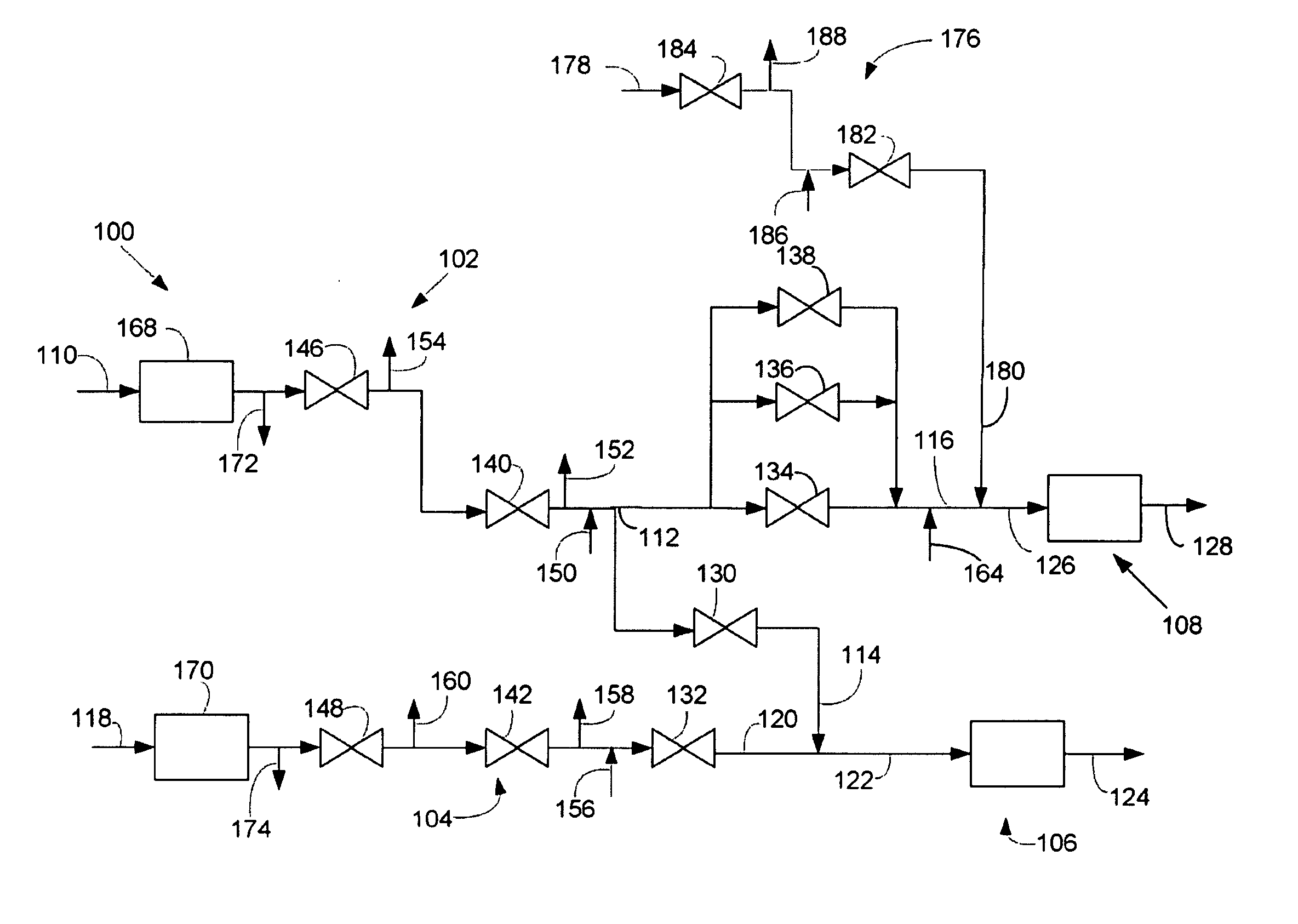
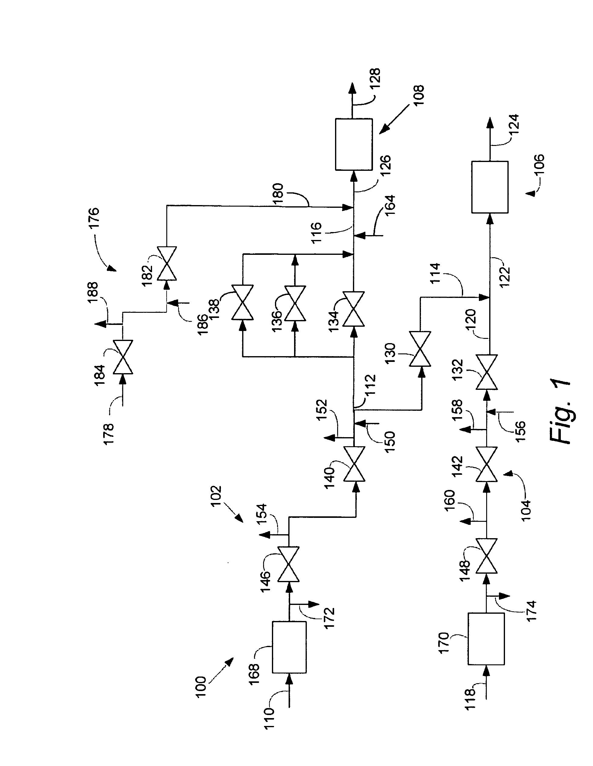
[0008]The present application provides a dual gas fuel delivery system and a method of operating the system.

[0009]I. Primary Manifold Dual Gas Fuel Delivery System

[0010]Referring now to the drawings, FIG. 1 shows a configuration of a primary manifold dual gas fuel system 100. The system 100 may be used to deliver a high-energy gas, a low energy gas, or a mixture of the high-energy gas and the low energy gas a turbine. Importantly, the system 100 may deliver both high-energy fuel and low energy fuel while only allowing the high-energy fuel to enter a single manifold. By delivering the high-energy fuel to only a single manifold, the system 100 may reduce the amount of energy stored in the manifolds and thereby reduce the risk of turbine over-speed.

[0011]The Gas Fuels

[0012]They system 100 may deliver a high-energy gas, a low energy gas, or a mixture of high-energy gas and low energy gas. The high-energy gas may have an energy value in a range from about 750 to about 2000 BTU / ft3, even ...


PUM


Abstract

The present application provides a method of operating a dual gas fuel delivery system comprising selecting a manifold and fuel flow split; setting the stroke of a high-energy gas control valve based on the fuel split; measuring the primary manifold nozzle pressure ratio across a primary manifold nozzle outlet; comparing the primary manifold nozzle pressure ratio against a primary manifold specification limit; adjusting the stroke of a primary low energy gas control valve to maintain the pressure ratio across the primary manifold nozzle outlet within the primary manifold specification limit; measuring the secondary manifold nozzle pressure ratio across a secondary manifold nozzle outlet; comparing the secondary manifold nozzle pressure ratio against a secondary manifold specification limit; and adjusting the stroke of a secondary low energy gas control valve to maintain the pressure ratio across the secondary manifold nozzle outlet within the secondary manifold specification limit.

Description

CROSS-REFERENCE TO RELATED APPLICATIONS[0001]The present application relates to U.S. patent application Ser. No. ______ entitled “Single Manifold Dual Gas Turbine Fuel System;” U.S. patent application Ser. No. ______ entitled “Independent Manifold Dual Gas Turbine Fuel System;” and U.S. patent application Ser. No. ______ entitled “Primary Manifold Dual Gas Fuel System.” These applications are incorporated herein by reference.TECHNICAL FIELD[0002]The present application relates to gas turbine fuel systems and more particularly relates to methods of operating gas turbine fuel systems capable of delivering two or more gaseous fuels to a single manifold.BACKGROUND OF THE INVENTION[0003]Modern gas turbines require precise control of the fuel system. For example, a pressure drop across the fuel nozzles must be carefully maintained within a specified range in order to avoid combustor damage. In general, it may be difficult to operate a modern gas turbine on a normal, high-energy fuel (for ...

Claims


Application Information

Patent Timeline
IPC IPC(8): F02C3/20
CPCF02C3/22F02C9/40F02C7/222F05D2270/3013F23R3/36F05D2220/75F02C7/232
Inventor ALEXANDER, MICHAEL J.JOSHI, RAHUL MOHANIASILLO, ROBERT J.MORANKAR, JITENDRA
Owner GENERAL ELECTRIC CO
Why Eureka
Try Eureka