Bone cutting device and method of using same

a cutting device and bone technology, applied in the field of drilling and cutting devices, can solve the problems of difficult positioning of the initial opening using the osteotome, and difficulty in keeping the osteotome in the desired position during the initial hammering

Inactive Publication Date: 2009-11-05
MILLER KENNETH
View PDF14 Cites 61 Cited by
  • Summary
  • Abstract
  • Description
  • Claims
  • Application Information

AI Technical Summary

Problems solved by technology

This can be a particular problem in the area beneath the sinus cavity.
This method requires bone to be harvested from a donor site, such as by use of a trephine drill, and has various risks associated with it related to the breaking of the bone in the side wall of the sinus cavity.
One problem associated with any procedure using an osteotome is the accurate placement of

Method used


Image

  • Bone cutting device and method of using same
  • Bone cutting device and method of using same
  • Bone cutting device and method of using same

Examples


Embodiment Construction

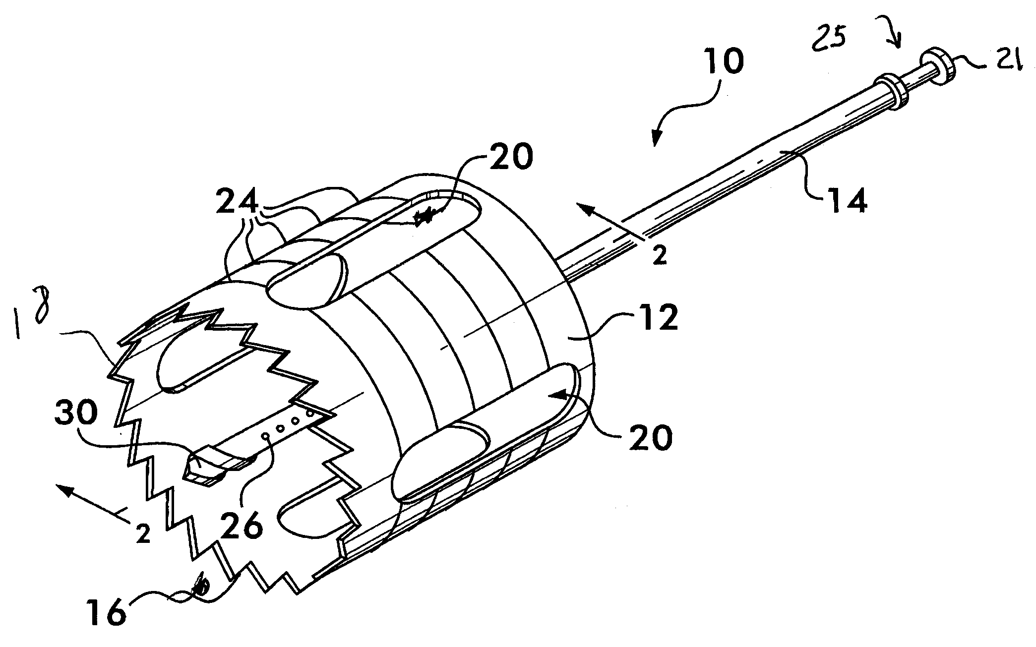
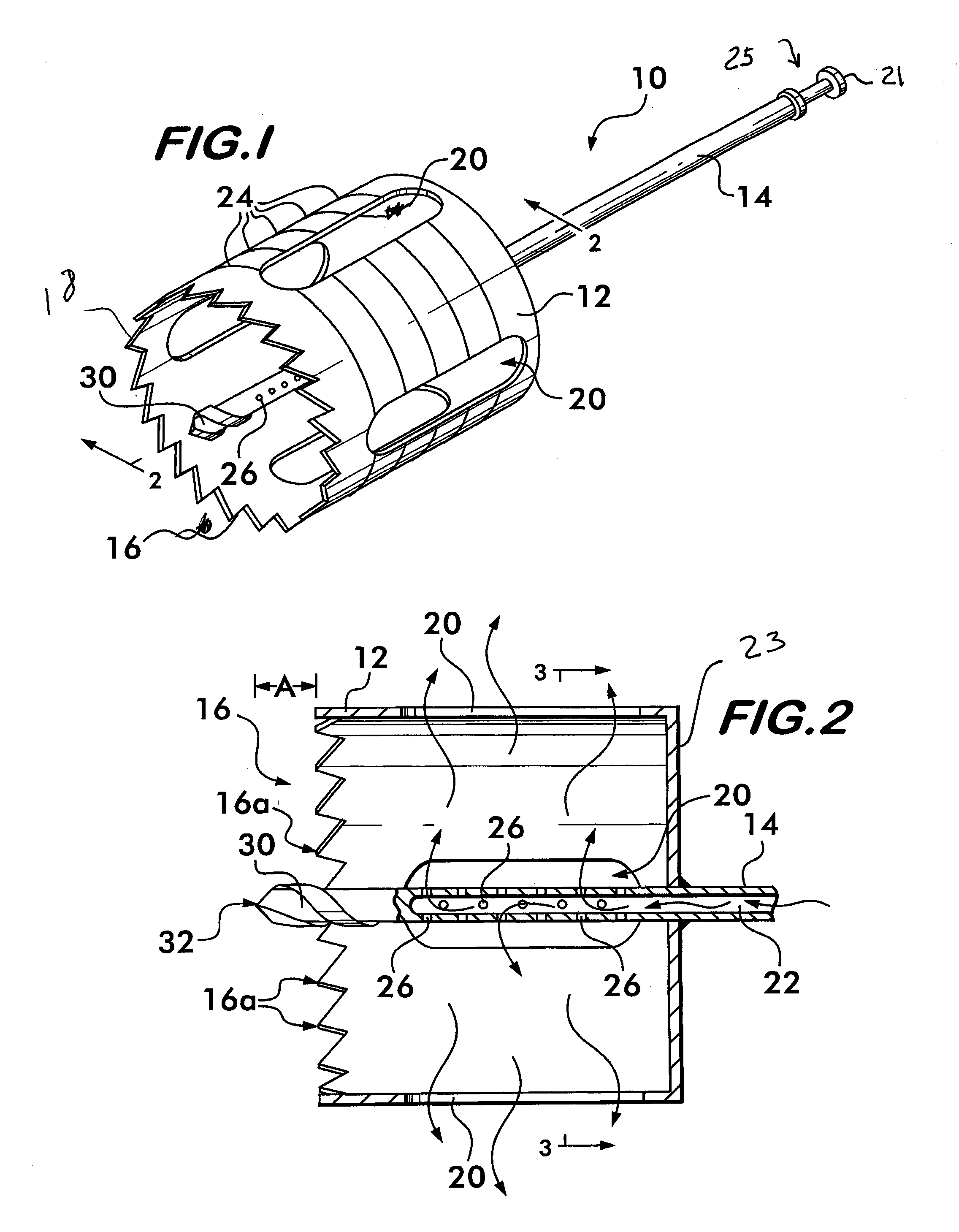
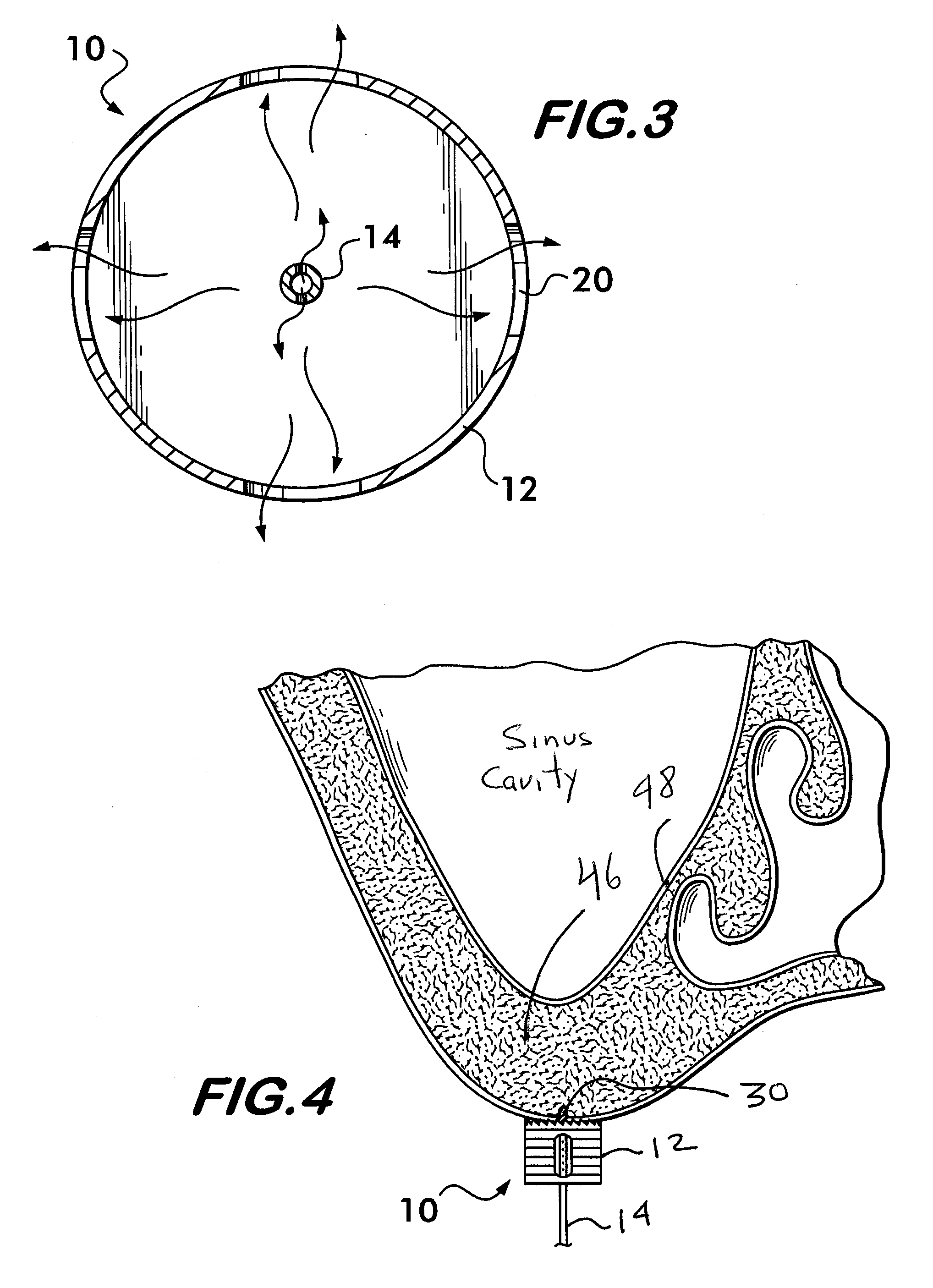
[0018]FIGS. 1-3 show an exemplary device 10 in accordance with the present invention configured for use with dental implant procedures. As shown in FIGS. 1-3, the exemplary device 10 resembles in part a conventional trephine in that it includes a tubular body 12, such as a thin cylinder of surgical grade stainless steel, fixedly supported at one end on a shaft 14 configured for receipt in a chuck of a surgical drill, such standard connection means to a surgical drill being well known in the art. Such surgical drills are known in the art, such as those used with conventional trephines. An opposite end of the body 12 supports a plurality of cutting teeth 16 arranged about the body's edge 18 as shown. The body 12 may include circumferentially-extending grooves or other depth-of-cut markings 24 (FIG. 1) at regular longitudinally spaced intervals to indicate cut depths. Openings 20 may be provided in the body 12 to promote cooling resulting from use of the device 10. Any suitable configu...


PUM


Abstract

A bone cutting device having a cylindrical body that has cutting teeth on one end, a shaft extending from another end of the body for attachment to a drill, which shaft can provide cooling water to the body, and a drill extending beyond the cutting teeth for contacting the bone prior to the cutting teeth contacting the bone.

Description

FIELD OF THE INVENTION [0001]The present invention relates generally to drilling and cutting devices, and more particularly to devices for making precisely-placed openings in bone, such as for preparation of dental implant sites.BACKGROUND OF THE INVENTION [0002]There are various methods for preparing dental implant sites. These are typically cylindrical openings formed in the patient's bone, such as in the alveolar bone of the maxilla, which can receive the implant via procedures well known in the art.[0003]For patients with an alveolar bone thickness of more than about 5 millimeters, a dental implant can be secured in a relatively stable manner using the existing bone. Here an implant drill can be used to create the implant site in a known manner.[0004]For patients with less than about 5 millimeters alveolar bone thickness, however, dental surgeons can use various procedures to build up the thickness of the alveolar bone so that the dental implant may be installed securely therein...

Claims


Application Information

Patent Timeline
IPC IPC(8): A61C3/02A61C1/00
CPCA61C1/084A61C8/0092A61C8/0089A61C3/02
Inventor MILLER, KENNETH
Owner MILLER KENNETH
Why Eureka
Try Eureka