Method of Optimizing Power Consumption in A Wireless Device

a wireless device and power consumption technology, applied in the field of communication devices, can solve the problems of increased power demands, inconvenient inoperative devices, and variable rate of battery power consumption

Active Publication Date: 2009-11-05
MOTOROLA SOLUTIONS INC
View PDF16 Cites 29 Cited by
  • Summary
  • Abstract
  • Description
  • Claims
  • Application Information

AI Technical Summary

Problems solved by technology

While many devices have a battery level indicator, the indication of low battery level can often be missed leading to the inconvenience of an inoperative device.
The wider array of functional capabilities may lead to increased power demands and

Method used


Image

  • Method of Optimizing Power Consumption in A Wireless Device
  • Method of Optimizing Power Consumption in A Wireless Device
  • Method of Optimizing Power Consumption in A Wireless Device

Examples


Embodiment Construction

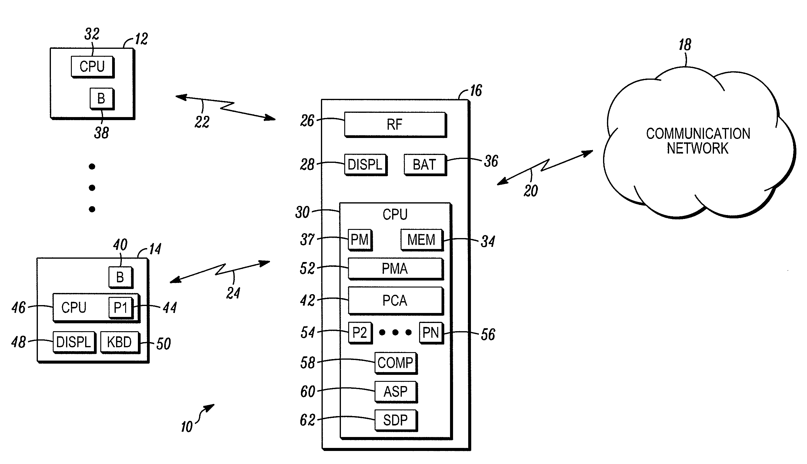
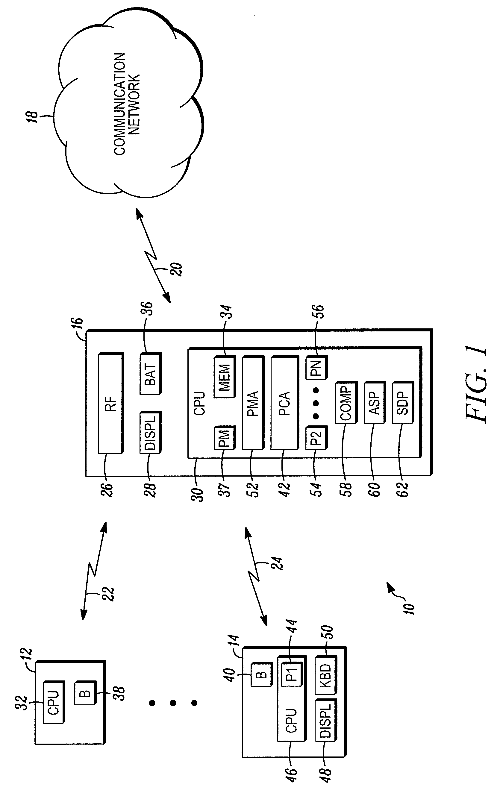
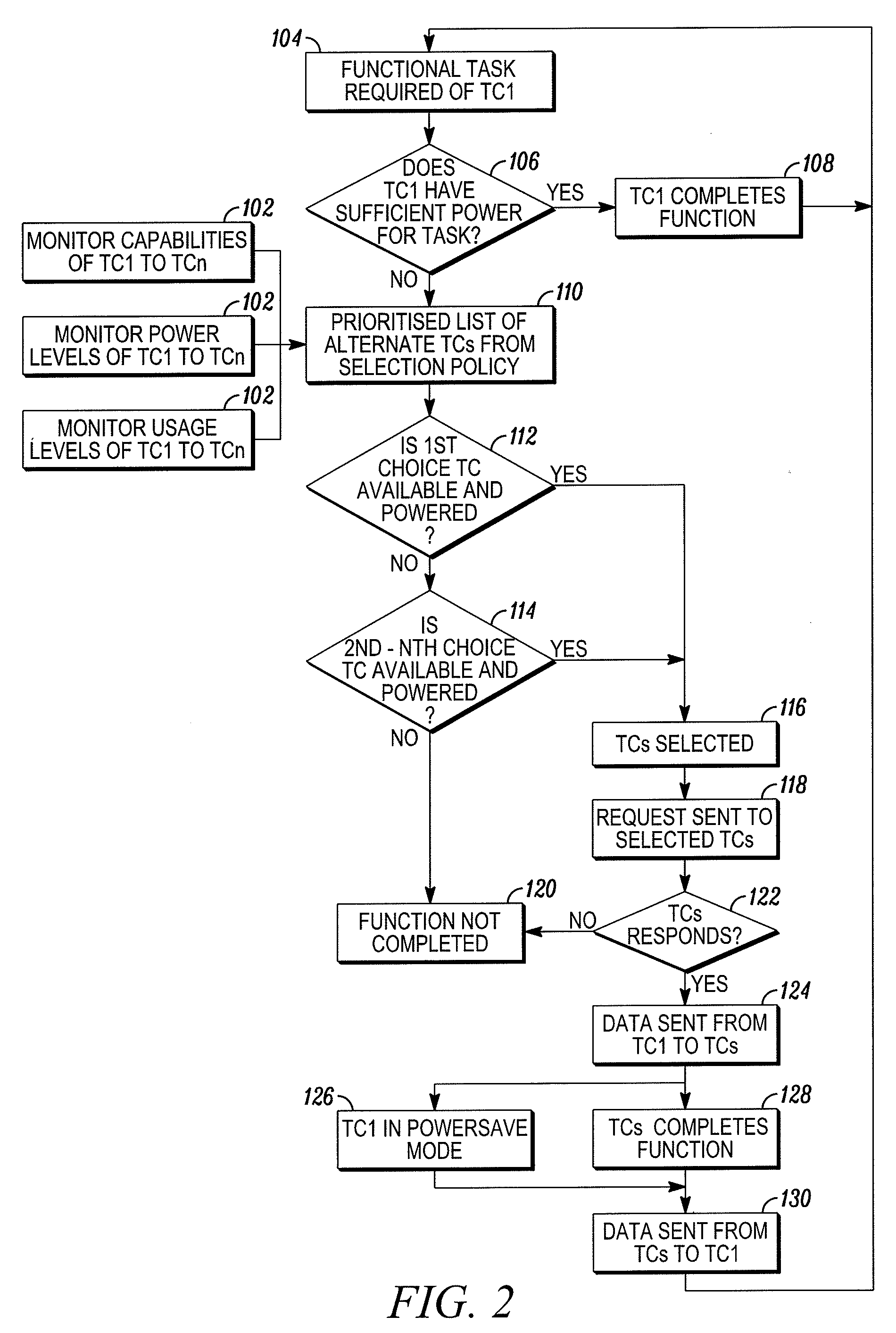
[0010]FIG. 1 is a block diagram of a communication device 10 shown generally in accordance with an illustrated embodiment of the invention. FIG. 2 is a flowchart of method steps that may be followed by the device 10 of FIG. 1.

[0011]The communication device 10 includes a transceiver (smart) module 16 and one or more peripheral devices (thin clients) 12, 14. The transceiver module 16 is a dual capability transceiver device that can simultaneously exchange communicated signals on each of a pair of two-way channels. In this regard, the transceiver 16 can exchange two-way communicated signals under a first format and in a first frequency range (e.g., a cellular) with a local base station (not shown) of a local cellular communication network 18. The transceiver module 16 may also simultaneously exchange two-way communicated signals under a second format and in a second frequency range (e.g., Bluetooth) with each of the respective thin clients 12, 14.

[0012]The smart transceiver module 16 a...


PUM


Abstract

A method and apparatus are provided for operating a wireless communication device. The method includes the steps of providing a plurality of battery powered modules that are carried by a user and together operate as the wireless communication module (ensemble), detecting a battery reserve power level of a first module of the plurality of modules and transferring a processing function from the first module to a second module of the plurality of modules based upon the detected battery reserve power.

Description

FIELD OF THE INVENTION[0001]The field of the invention relates to communication devices and more particularly to wireless devices.BACKGROUND OF THE INVENTION[0002]Wireless communication devices are generally known. Wireless devices may be divided by function into voice devices such as cellular telephones and data devices such as PDAs or portable computers with wireless interfaces. Recent advances also include a large number of “smart” portable wireless devices that are able to handle both voice and data and typically have a wide range of functional capabilities.[0003]When a wireless device is activated, the device automatically begins searching for a local base station. In order to facilitate the search for a base station, the base stations may transmit identification messages on one or more control channels. In order to locate a control channel of a local base station, the device may scan a series of channels by individually stopping on each channel and decoding any information on ...

Claims


Application Information

Patent Timeline
IPC IPC(8): H04M1/00H04M1/72412
CPCH04M1/0256H04W4/20H04W52/0261H04M1/7253Y02D30/70H04M1/72412
Inventor REINISCH, WILLIAMWATSON, CRAIGWHEATLEY, DAVIDNARASIMHAN, NITYA
Owner MOTOROLA SOLUTIONS INC
Why Eureka
Try Eureka