Tool for removing a chisel

a technology for removing tools and chisels, which is applied in the field of tools for removing chisels, can solve the problems of inability to perform a removal of chisels, time-consuming, and difficult manipulation of double levers, and achieve the effect of simple and rapid exchang

Active Publication Date: 2009-12-03
WIRTGEN GMBH
View PDF17 Cites 38 Cited by
  • Summary
  • Abstract
  • Description
  • Claims
  • Application Information

AI Technical Summary

Benefits of technology

[0010]It is one object of this invention to provide a tool of the type mentioned above but in which chisels can be simply and rapidly exchanged.
[0015]Preferably, those locations on the chisel holder are used for the support, which are not subject to excessive wear, so that the tool can always be placed in a reproducible manner. The wear disk in particular, which is customarily arranged between the chisel head and a support surface of the chisel holder, provides an ideal support location.
[0019]This simple structural design makes possible the stable guidance of the actuating member between the two lateral walls.
[0021]In case of an appropriate limitation, the actuating member is positioned by a stop in its initial position so that the easy placement against the chisel holder is possible. The limitation of the actuating movement of the actuating member in the removal position prevents the actuating member from becoming jammed in the chisel receiver.
[0022]In particular, the actuating member can be movable out of its initial position into the removal position, and the actuating member can be maintained in a spring-loaded manner in its initial position by a spring element. This step assures that, when the cylinder is switched to no pressure, the actuating member remains in its initial position, or respectively returns into it. For example, in case of the use of a double-acting cylinder, it is possible to do without the spring-loading.

Problems solved by technology

In the restricted assembly space, the manipulation of the double lever is difficult and is time-consuming.
Further, the tool requires a support shoulder on the milling roller, which is not always available.
It is not possible to perform a removal of the chisels, if the chisel heads are worn to such a large extent that the groove is no longer sufficiently available.
Also, chisels with broken-off chisel heads cannot be removed.
The plunger, which is structurally connected with the chisel holder, constitutes an additional part and assembly cost.
Further, it requires an increase in the structural space in the chisel holder, which is not always acceptable in connection with modern precision milling machines.
Also, this type of construction requires the fixation of the chisel in a blind hole-like chisel receiver which can become soiled during operation, which leads to a loss of the system.

Method used


Image

  • Tool for removing a chisel
  • Tool for removing a chisel
  • Tool for removing a chisel

Examples


Embodiment Construction

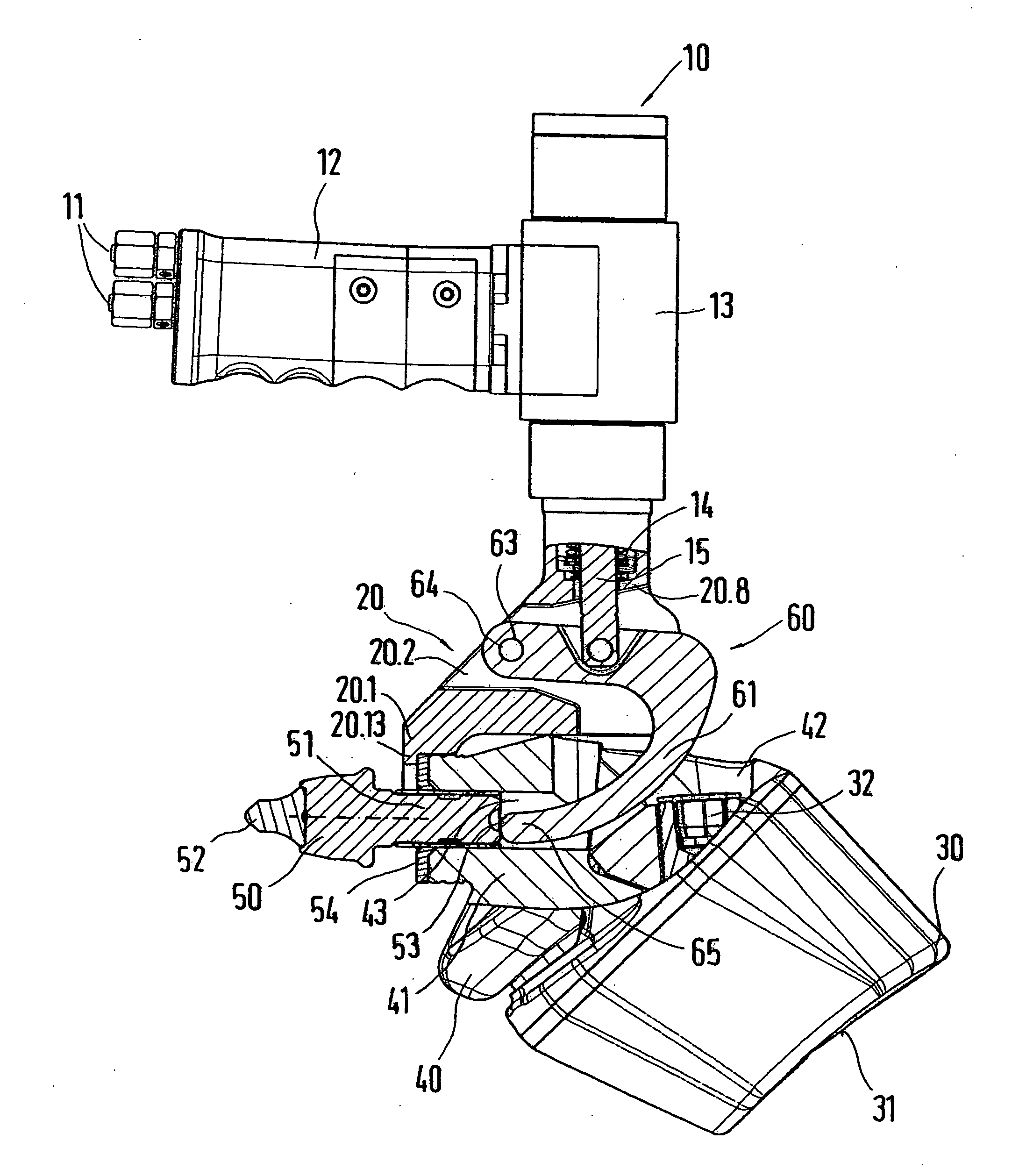
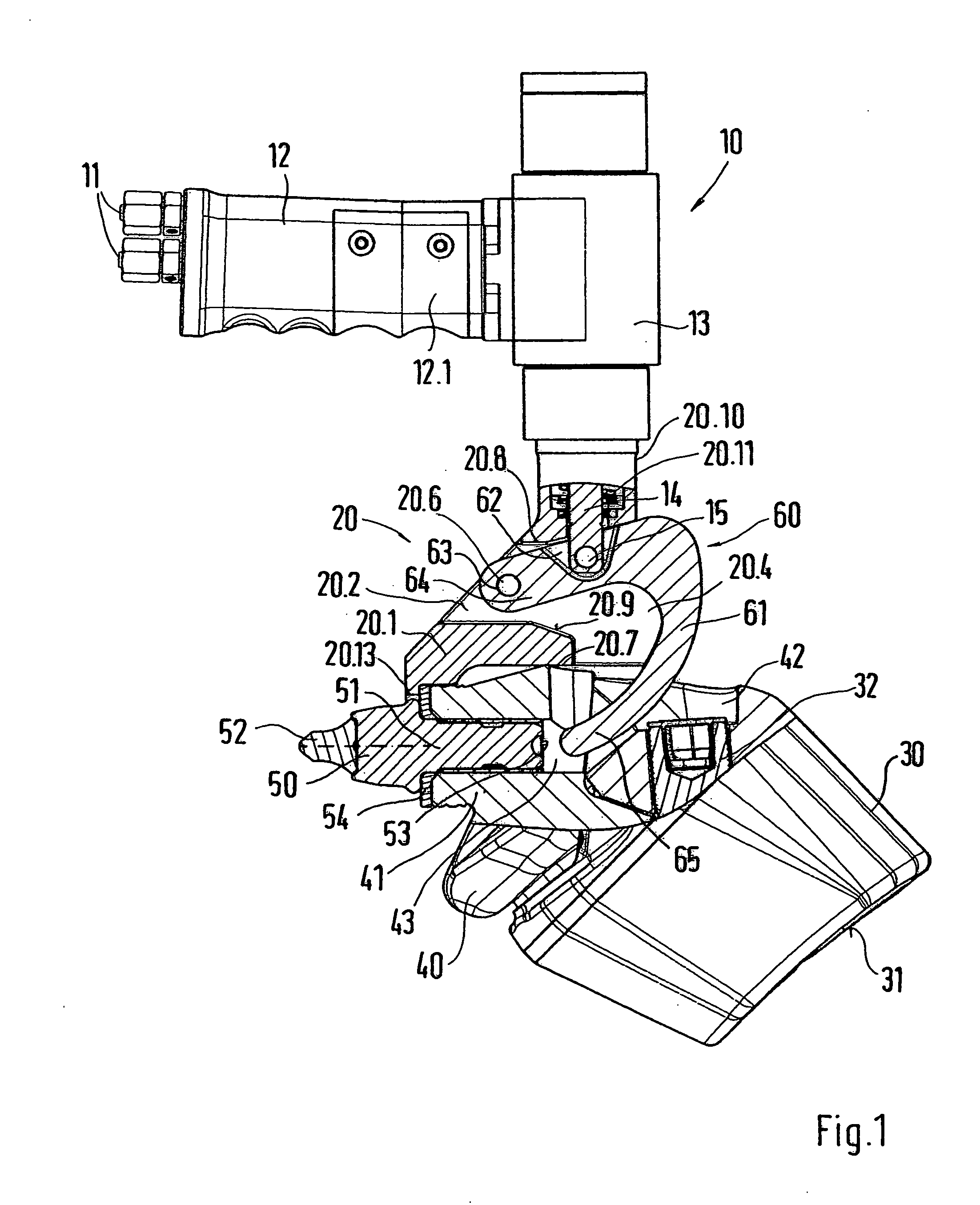
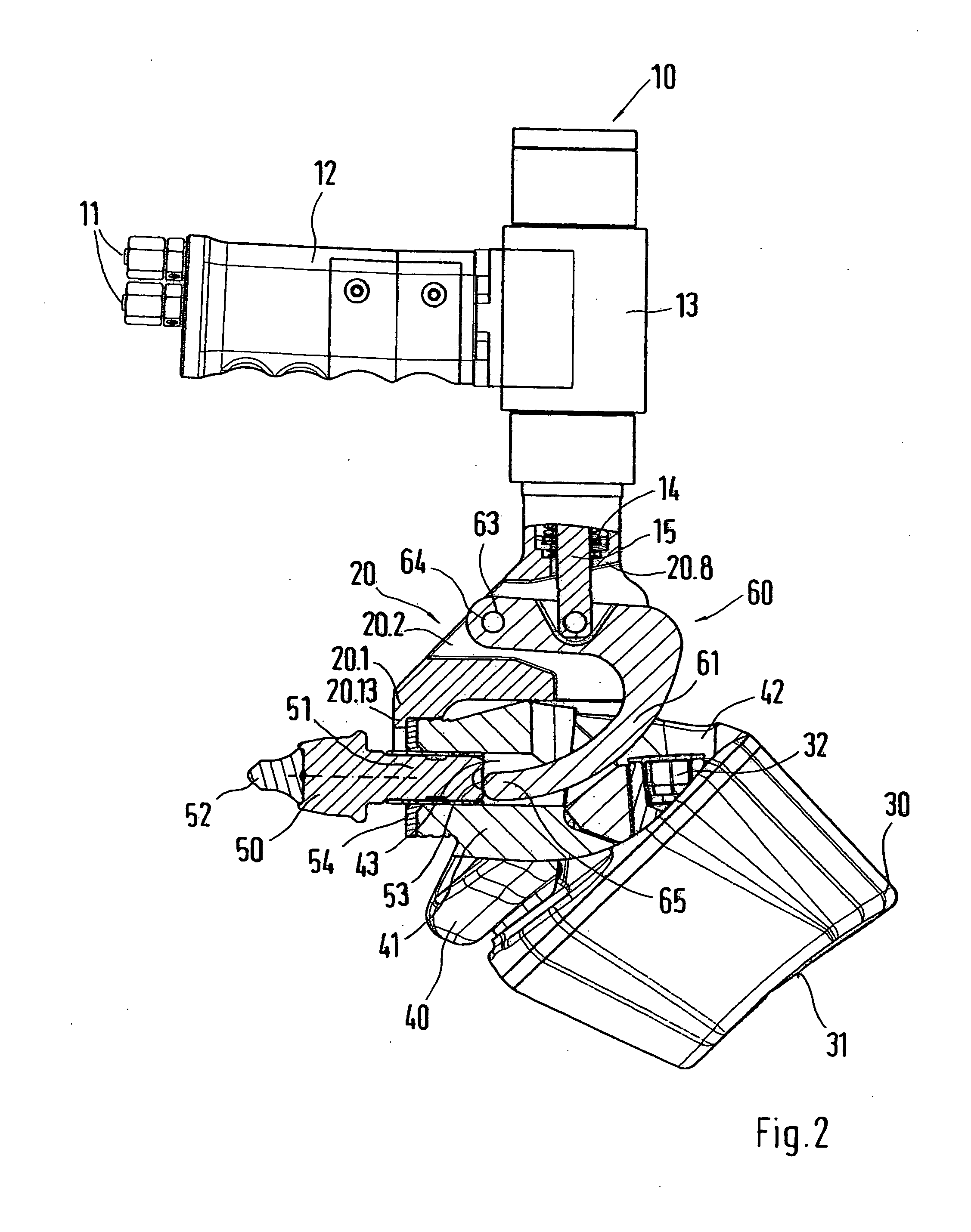
[0034]FIG. 1 shows a tool 10 with a handle 12. A battery is integrated into the handle 12. The battery can be charged in an appropriate charging station via two electrical current contacts 11. The battery is used for supplying electrical current to an electric motor. The electric motor is contained in a housing attachment, which is connected to the handle 12. A cylinder 13 is contained in this housing attachment. The cylinder 13 can be embodied as a hydraulic cylinder, so that an appropriate hydraulic circuit system is integrated into the housing attachment. A piston is seated in the cylinder 13 and is displaceable between two end positions. A trigger 12.1 is installed on the handle 12. The trigger 12.1 closes a contact of an electrical circuit and thus activates the electric motor in the housing attachment. The electric motor, together with the hydraulic system, causes the displacement of the piston in the cylinder 13. Alternatively, it is possible to integrate lines into the handl...


PUM

PropertyMeasurementUnit
displacement movementaaaaaaaaaa
flexural strengthaaaaaaaaaa
lever displacementaaaaaaaaaa

Abstract

A tool for removing a chisel, in particular from a chisel holder, having a base element which receives an actuating member, wherein the actuating member has an expeller mandrel. The actuating member is adjustable along a displacement direction. In order to be able to perform the removal simply and rapidly, the actuating member of this invention is indirectly or directly coupled to a piston of a fluid-charged cylinder, or to an electric motor unit.

Description

BACKGROUND OF THE INVENTION[0001]1. Field of the Invention[0002]This invention relates to a tool for removing a chisel, in particular from a chisel holder, having a base element which receives an actuating member, wherein the actuating member has an expeller mandrel, and the actuating member is adjustable.[0003]2. Discussion of Related Art[0004]Similar tools are employed, for example, in connection with road milling machinery, recyclers, surface miners, and the like. They are used for removing chisels, in particular shank chisels, such as round shank chisels. In this case, the chisels are clampingly held in chisel receivers. Customarily, the chisel receivers are designed as through-bores. The chisel holders themselves are fastened to the surface of a milling roller tube, in particular welded to it, or are interchangeably fixed in base supports, which also are welded to the surface of a milling roller tube. Tools are known for making the removal of the chisels easier, such as are des...

Claims


Application Information

Patent Timeline
Patent Type & Authority Applications(United States)
IPC IPC(8): B25B27/02B23P19/027
CPCE21C35/19E21C2035/1826Y10T29/53909Y10T29/5383Y10T29/53704Y10T29/49822B25B27/023B25B27/026E02F9/2891E21C35/188
Inventor LEHNERT, THOMASLENZ, MARTINHOLL, BERNDHAHN, GUNTER
Owner WIRTGEN GMBH
Why Eureka
Try Eureka