Single switch high efficiency power supply

a single switch, high-efficiency technology, applied in the direction of electric variable regulation, process and machine control, instruments, etc., can solve the problems of somewhat selective output voltage but at the cost of complex variable frequency alternating operation of such two switches, and no design generally encompasses all desired characteristics, so as to achieve the effect of voltage regulation

Active Publication Date: 2009-12-03
ITRON
View PDF10 Cites 35 Cited by
  • Summary
  • Abstract
  • Description
  • Claims
  • Application Information

AI Technical Summary

Benefits of technology

[0022]In exemplary variations of the present power supply methodology, charging of the plurality of capacitors may be achieved during the negative half cycle of the AC input source by coupling an upper end of the first plurality of diodes to a ground potential and by forcing such ground potential to be relatively positive with respect to a lower end of the first plurality of diodes / capacitor string as the output of the AC input source goes through its negative half cycle; discharging of the plurality of capacitors may be achieved during the positive half cycle of the AC input source by closing the single switching element so as to discharge the plurality of capacitors through the second plurality of diodes, into a load associated therewith; and such power supply methodology may further include providing a filter capacitor in parallel with such load, to provide ripple filtering and to assist in voltage regulation of the low voltage DC produced by discharge of the capacitive voltage divider.

Problems solved by technology

Such form of operation results in a somewhat selectively variable output voltage but at the cost of complex variable frequency alternating operation of such two switches.
While various implementations of series-parallel capacitor-diode voltage dividing circuits have been developed, and while various combinations of AC to DC and DC to DC voltage divider circuits have been developed, no design has emerged that generally encompasses all of the desired characteristics as hereafter presented in accordance with the subject technology.

Method used


Image

  • Single switch high efficiency power supply
  • Single switch high efficiency power supply
  • Single switch high efficiency power supply

Examples


Embodiment Construction

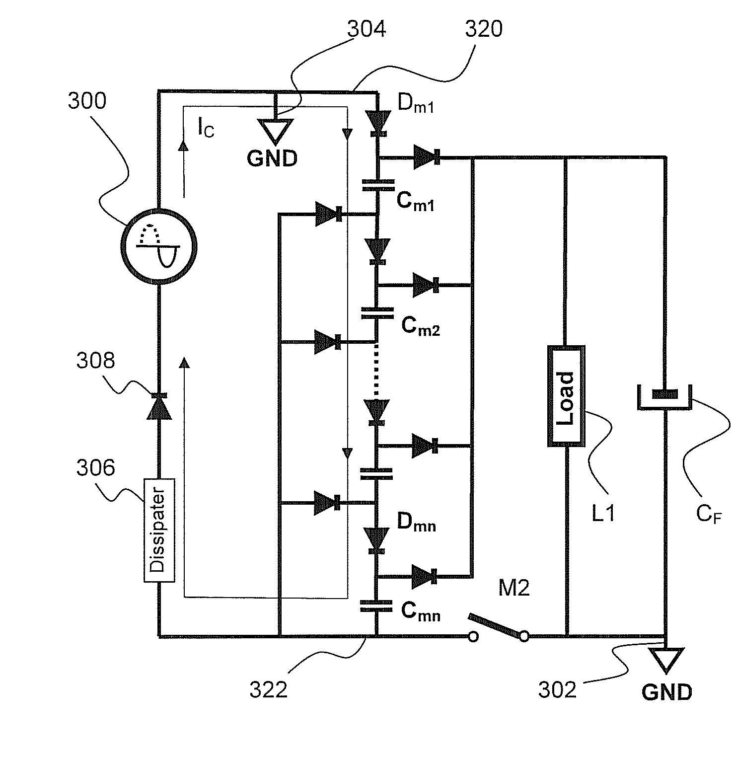
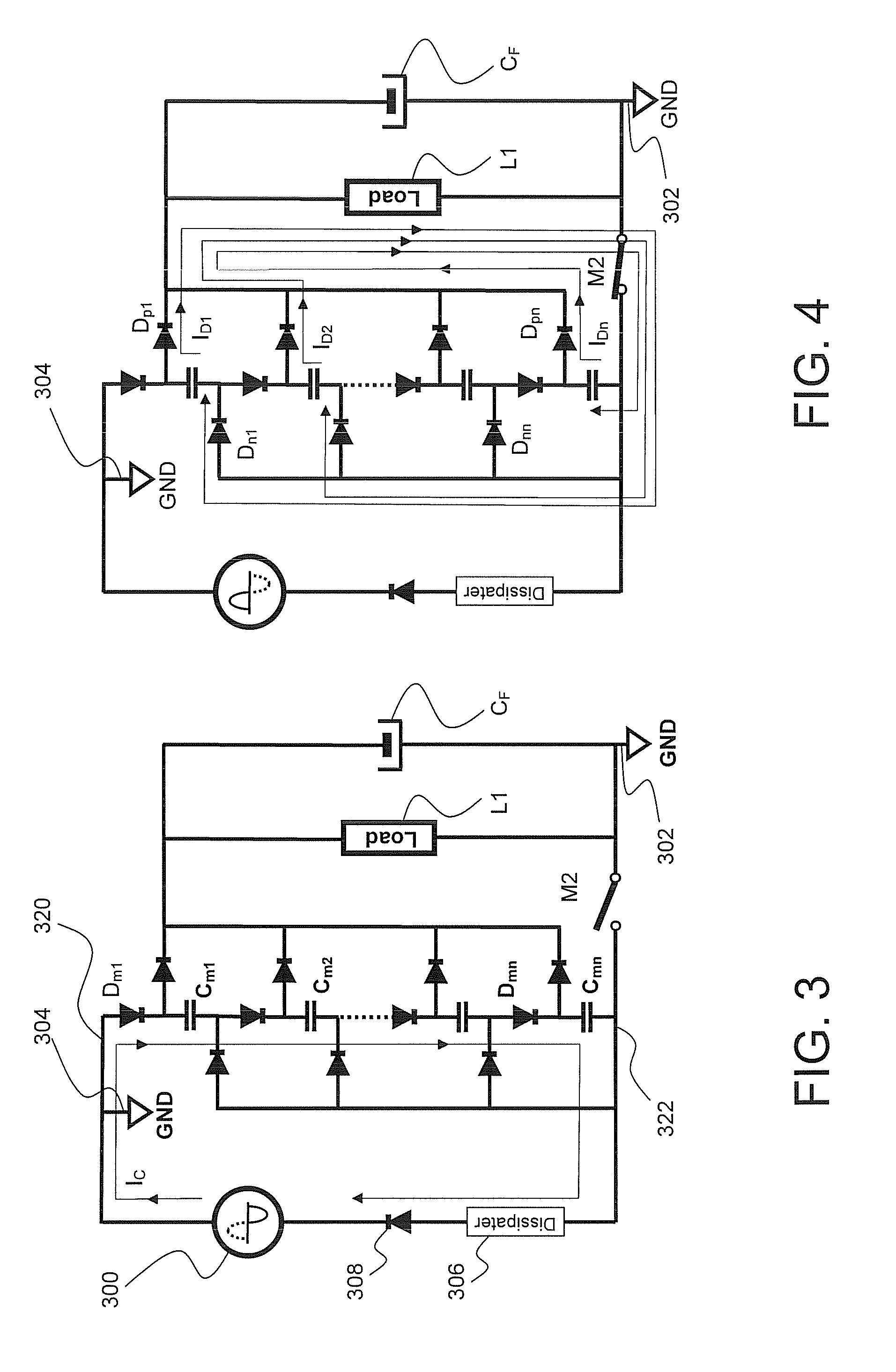
[0033]As referenced in the Summary of the Invention section, the present subject matter is particularly concerned with an improved single switch series-parallel capacitor-diode voltage dividing circuit.

[0034]Selected combinations of aspects of the disclosed technology correspond to a plurality of different embodiments of the present subject matter. It should be noted that each of the exemplary embodiments presented and discussed herein should not insinuate limitations of the present subject matter. Features or steps illustrated or described as part of one embodiment may be used in combination with aspects of another embodiment to yield yet further embodiments. Additionally, certain features may be interchanged with similar devices or features not expressly mentioned which perform the same or similar function.

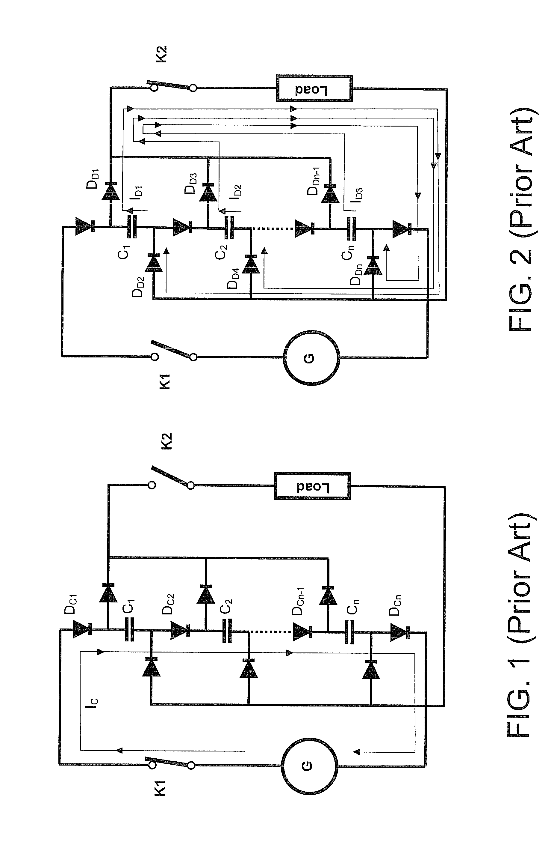
[0035]Referring now to the drawings, and with initial reference to FIGS. 1 and 2, there is illustrated the operation of a generally known capacitive divider circuitry. As illust...


PUM


Abstract

Disclosed are apparatus and methodology for providing a capacitive voltage divider configured to reduce a relatively high level alternating current (AC) to a lower level direct current (DC). The apparatus provides a series of capacitors and diodes configured for series charging of the capacitors and parallel discharge thereof by way of a single switching element. In operation, the capacitor series is charged during the negative half cycle of the AC source and then discharged during the positive half cycle thereof.

Description

PRIORITY CLAIM[0001]This application claims the benefit of previously filed U.S. Provisional Patent Application entitled “Single Switch Unregulated Inductorless High Voltage High Efficiency Power Supply,” assigned U.S. Ser. No. 61 / 057,589, filed May 30, 2008, and which is incorporated herein by reference for all purposes.FIELD OF THE INVENTION[0002]The present subject matter relates to power supplies. More particularly, the present subject matter relates to a series charge, parallel discharge capacitor power supply requiring only a single switch and no inductor in order to shift from charge mode to discharge mode.BACKGROUND OF THE INVENTION[0003]Power supplies constructed using the known concept of serially charging a series of capacitors and discharging the series in parallel are known in the art. Such configurations may be used, for example, with variations in excitation, for a variety of configurations. In one example, U.S. Pat. No. 5,446,644 (Zhou) discloses a direct current (DC...

Claims


Application Information

Patent Timeline
Patent Type & Authority Applications(United States)
IPC IPC(8): H02M3/06
CPCH02M7/103
Inventor BORISOV, VLADIMIR
Owner ITRON
Why Eureka
Try Eureka