
Vacuum device and method for packaging same

a vacuum device and vacuum technology, applied in the field of vacuum devices and methods for packaging the same, can solve the problems of increased manufacturing cost, disadvantageous prepackaged containers with respect to safety and reliability, and complicated structure of packaged containers

Active Publication Date: 2009-12-24
TSINGHUA UNIV +1
View PDF16 Cites 15 Cited by
  • Summary
  • Abstract
  • Description
  • Claims
  • Application Information

AI Technical Summary

Problems solved by technology

However, the prepackaged container is disadvantageous with respect to safety and reliability because the exhaust pipe 110 needs to be disposed on the through hole 102 of the pre-packaged container 100, and the exhaust pipe 110 is retained outside of the packaged container.
Therefore, the structure of the packaged container becomes complicated and the manufacturing cost is increased.

Method used


Image

  • Vacuum device and method for packaging same
  • Vacuum device and method for packaging same
  • Vacuum device and method for packaging same

Examples


Embodiment Construction

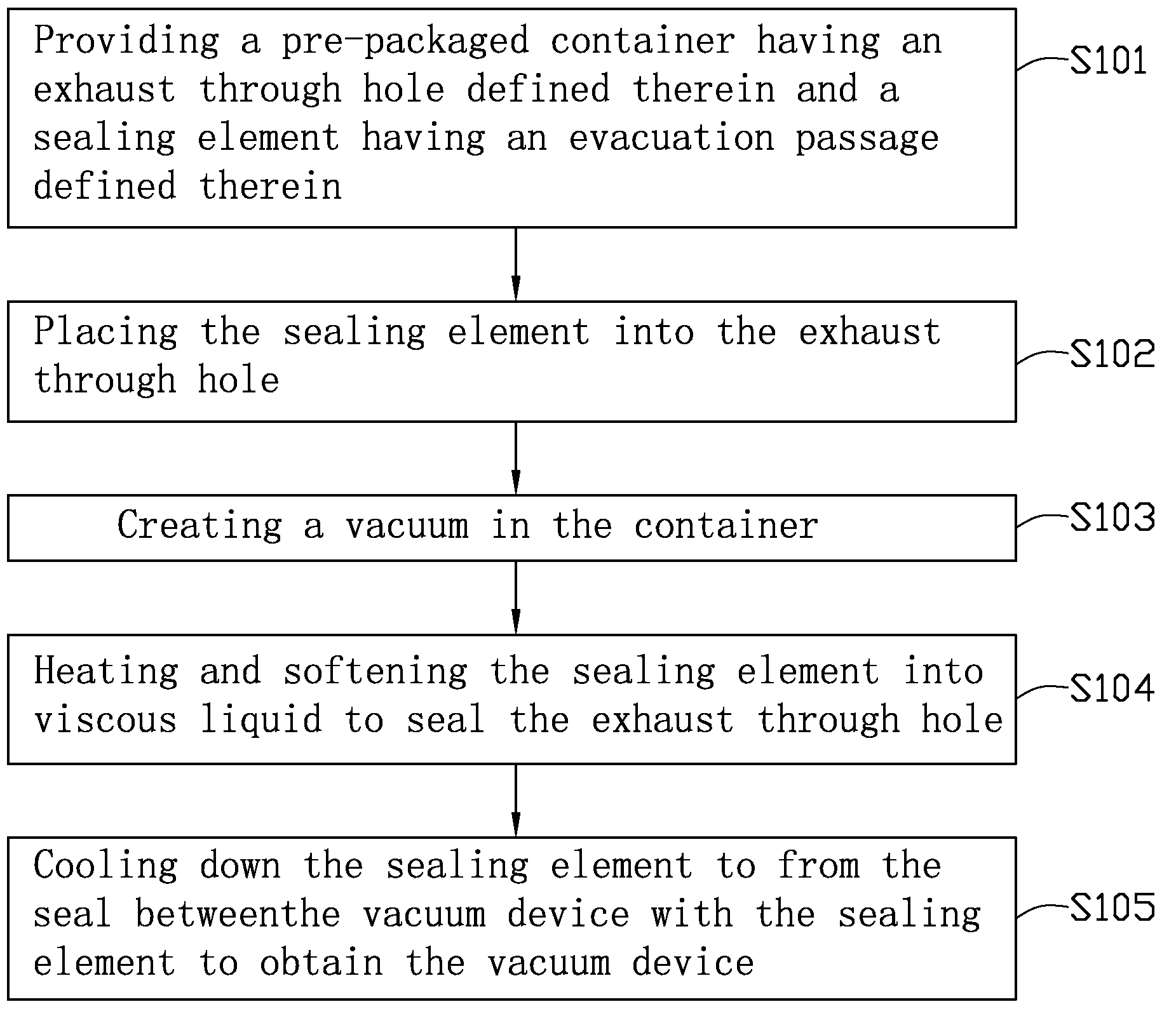
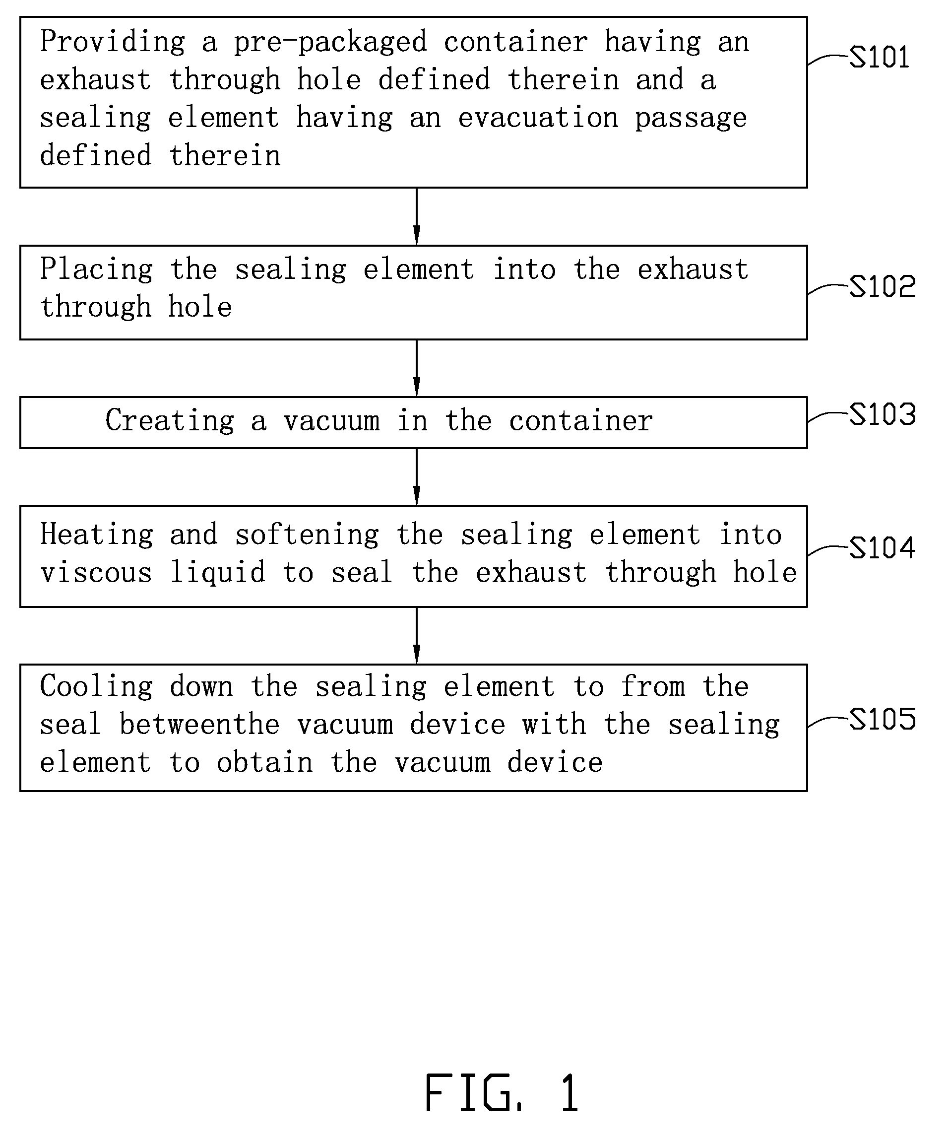
[0017]Referring to FIGS. 1-2 and 3A-3C, a method of packaging a vacuum device is shown. Depending on the embodiment, certain of the steps described below may be removed, others may be added, and the sequence of steps may be altered. It is also to be understood that the above description and the claims drawn to a method may include some indication in reference to certain steps. However, the indication used is only to be viewed for identification purposes and not as a suggestion as to an order for the steps. The method includes:

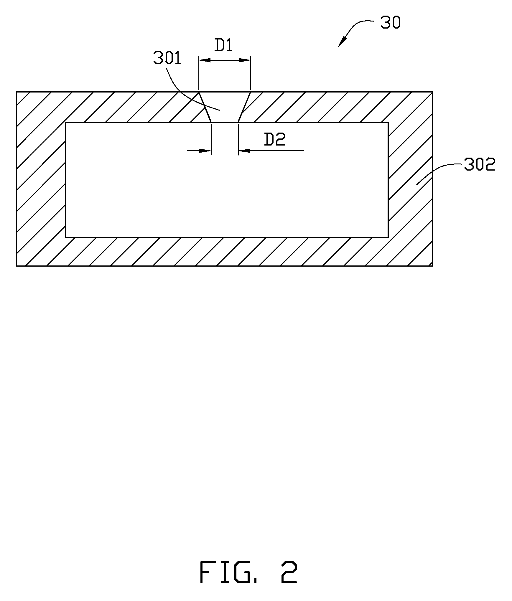
[0018]step S101: providing a pre-packaged container 30 having an exhaust through hole 301 defined therein and a sealing element 31 having a through hole 311 defined therein;

[0019]step S102: placing the sealing element 31 into the exhaust through hole 301;

[0020]step S103: creating a vacuum in the container 30;

[0021]step S104: heating and softening the sealing element 31 into viscous liquid to seal the exhaust through hole 301;

[0022]step S105: cooling down the se...


PUM


Abstract

A method for packaging the vacuum device includes providing a pre-packaged container having an exhaust through hole defined therein and a sealing element placed into the exhaust through hole, pumping the pre-packaged container to create a vacuum, heating and softening the sealing element to seal the exhaust through hole, and cooling the melted low-melting glass to package the pre-packaged container.

Description

BACKGROUND[0001]1. Technical Field[0002]The present disclosure relates to packaging technologies and, in particular, to a vacuum device and a method for packaging the same.[0003]2. Description of Related Art[0004]Some vacuum devices, such as flat panel displays, are packaged by a vacuum packaging system to create a vacuum within such devices. Referring to FIG. 7, a typical packaging method of a pre-packaged container 100 includes the following steps. The pre-packaged container 100, which has an exhaust through hole 102 defined therein, is prepared. An exhaust pipe 110 is provided. One end of the exhaust pipe 110 is inserted into and fixed in the through hole 102 via low-melting glass material 108, and another end of the exhaust pipe 110 is exposed outside of the pre-packaged container 100. A cup-shaped connector 104, which connects to a vacuum pump 106, is provided. The cup-shaped connector 104 covers the exhaust pipe 110 to create a vacuum in the pre-packaged container 100 via the ...

Claims


Application Information

Patent Timeline
IPC IPC(8): B65B31/00
CPCH01J5/24H01J29/862H01J29/94H01J2329/941H01J2211/54H01J2329/867H01J2211/48
Inventor GUO, CAI-LINLIU, PENGCHEN, PI-JINDU, BING-CHULIU, LIANGFAN, SHOU-SHAN
Owner TSINGHUA UNIV
Learn More