
Calibration techniques for MIMO wireless communication systems

a wireless communication system and wireless communication technology, applied in multi-frequency code systems, receiveer monitoring, duplex signal operation, etc., can solve problems such as reducing the effectiveness of the mimo system

Inactive Publication Date: 2009-12-31
MOTOROLA MOBILITY LLC
View PDF12 Cites 22 Cited by
  • Summary
  • Abstract
  • Description
  • Claims
  • Application Information

AI Technical Summary

Problems solved by technology

Therefore, such calibration techniques require excessive amounts of radio-frequency power (RF) to be generated and transmit

Method used


Image

  • Calibration techniques for MIMO wireless communication systems
  • Calibration techniques for MIMO wireless communication systems
  • Calibration techniques for MIMO wireless communication systems

Examples


Embodiment Construction

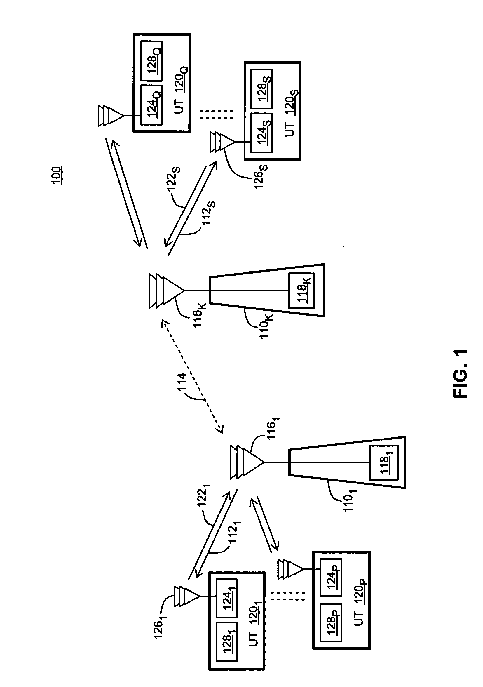
[0007]A method, apparatus and system for performing over-the-air calibration routines in a multiple-input multiple-output (MIMO) communication system are disclosed.

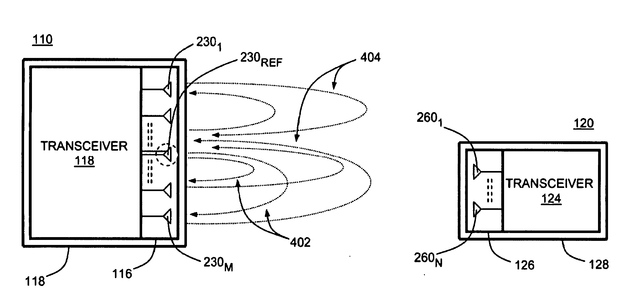
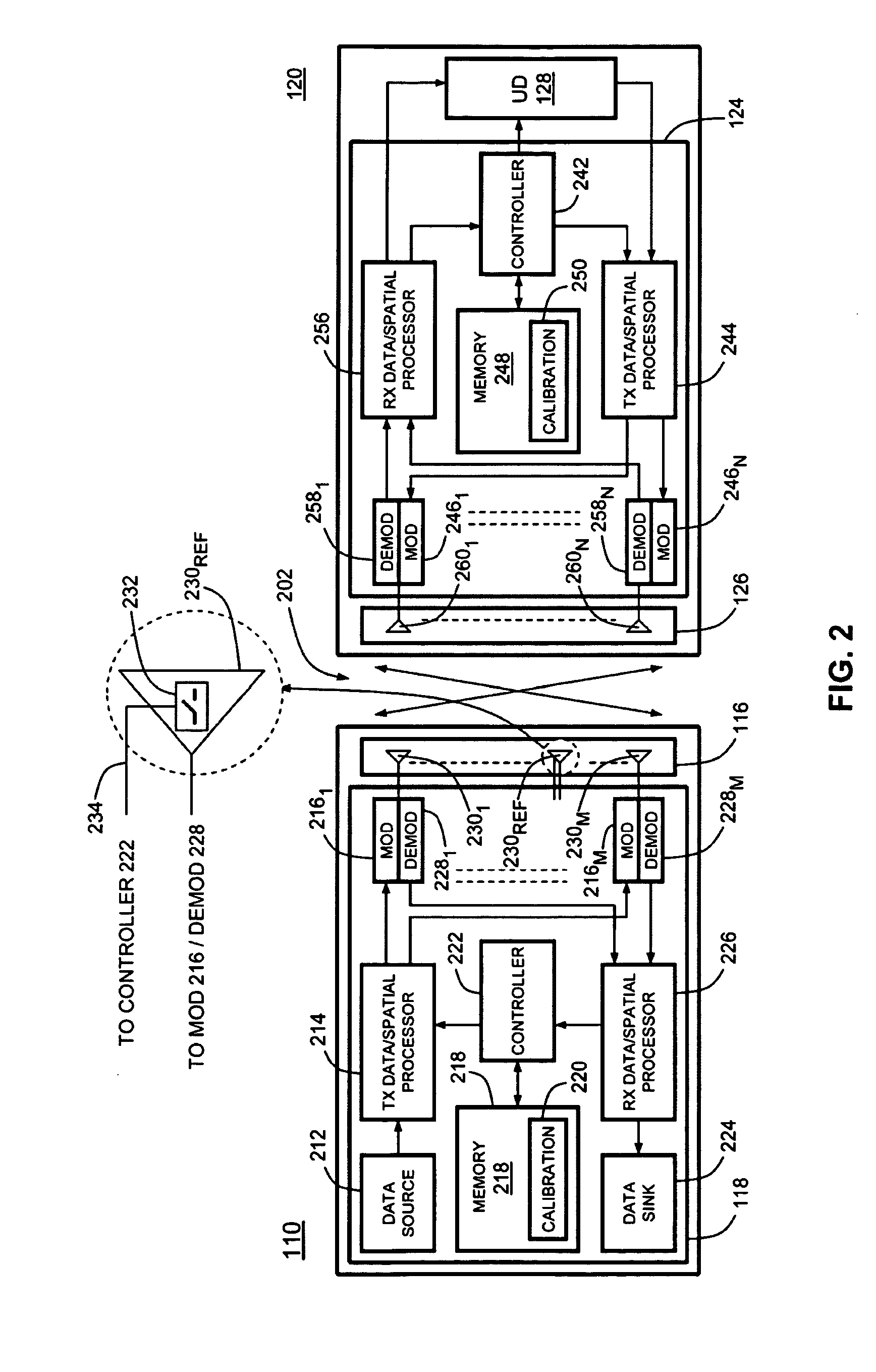
[0008]In embodiments of the present invention, an antenna array of a transceiver in the MIMO system (e.g., transceiver of a base station) comprises a re-configurable antenna. In a first state, CAL state, the antenna exhibits a first value of electromagnetic coupling to other antennas of the array, and in a second state, NoCAL state, the antenna exhibits a second value of the electromagnetic coupling to these antennas, which is different than the first value. In operation, the reference antenna is switched to the first state during uplink / downlink calibrating transmissions and switched to the second state during one of (i) uplink and downlink communications and (ii) channel sounding calibrating transmissions.

[0009]The above as well as additional features and advantages of the present invention will become apparent in the f...


PUM


Abstract

A method, apparatus and system for performing over-the-air calibration routines in a multiple-input multiple-output (MIMO) communication system. An antenna array of a transceiver (e.g., transceiver of a base station) comprises a re-configurable antenna having two switchable configuration states. The antenna exhibits different degrees of electromagnetic coupling to other antennas of the array in a first state than in a second state. The reference antenna is switched to the first state for performing uplink/downlink calibrating transmissions and switched to the second state during uplink and downlink communications or channel sounding calibrating transmissions.

Description

BACKGROUND[0001]1. Technical Field[0002]The present invention generally relates to wireless multiple-input multiple-output (MIMO) communication systems, and in particular to calibration techniques performed in MIMO communication systems.[0003]2. Description of the Related Art[0004]In general, wireless multiple-input multiple-output (MIMO) communication systems can offer larger channel transmission capacity and reliability than traditional single-input single-output (SISO) systems. A MIMO system employs multiple transmit / receive antennas and transmits data in parallel via an air MIMO channel comprising a plurality of individual spatial channels formed between transmitting and receiving parties, such as base stations and user terminals of the MIMO system.[0005]In operation, transmission characteristics, or responses, of the MIMO channels are often monitored. For example, a base station may need to know a response of uplink / downlink MIMO channels in order to optimize parameters of spat...

Claims


Application Information

Patent Timeline
IPC IPC(8): H04B1/38H04L27/28
CPCH01Q1/523H04B17/21H04B7/0413H01Q3/267
Inventor BURIS, NICHOLAS E.MUELLER, BRUCE D.VOOK, FREDERICK W.
Owner MOTOROLA MOBILITY LLC
Learn More