
Pleat-forming drapery clip ring

a drapery clip and pleat-forming technology, applied in the field of drapery hardware, can solve the problems of time-consuming, arduous, not particularly effective, and requiring specialized skill and knowledge, and achieve the effect of reducing the number of strands

Inactive Publication Date: 2010-01-28
UMBRA
View PDF5 Cites 6 Cited by
  • Summary
  • Abstract
  • Description
  • Claims
  • Application Information

AI Technical Summary

Benefits of technology

[0009]It is a general object of the present invention to provide a means for forming and maintaining pleats in the fabric of drapery that is not time-consuming, arduous, nor requires specialized skill and knowledge.

Problems solved by technology

Unfortunately, these methods are time-consuming, arduous, and not particularly effective as repeated movement and use of the drapery tends to deform the pleats.
Sewing is problematic in that it is both arduous and requires specialized skill and knowledge.
Additionally, while it may be desirable to fashion pleats in one's drapery, it may not be desirable to permanently alter the drapery by sewing the pleats into the fabric, especially if one wishes to later eliminate the pleats.

Method used


Image

  • Pleat-forming drapery clip ring
  • Pleat-forming drapery clip ring
  • Pleat-forming drapery clip ring

Examples


first embodiment

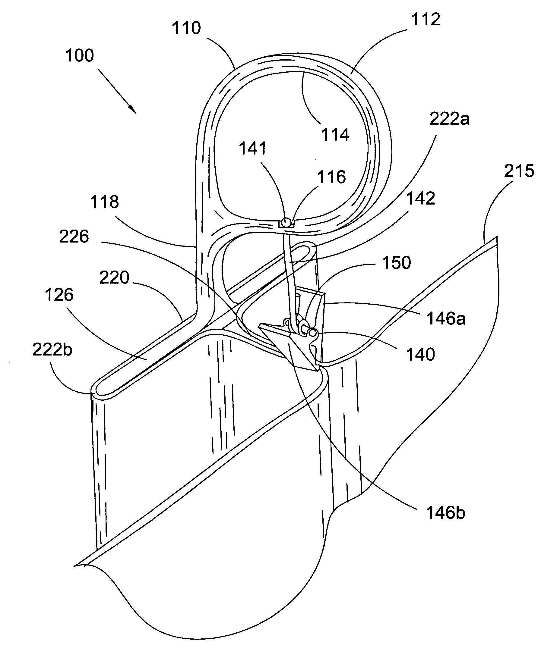
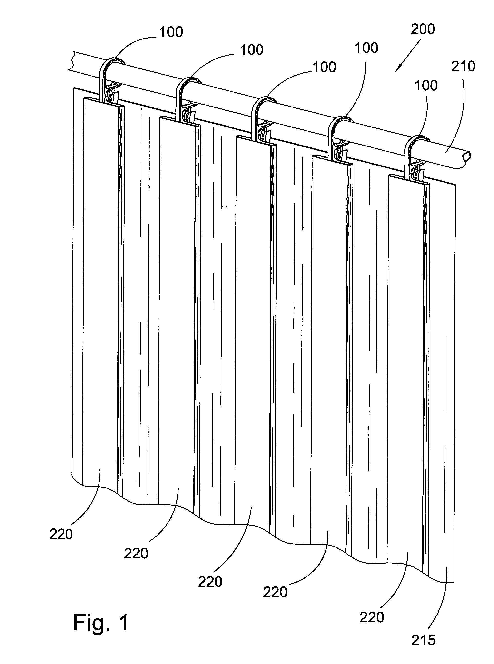
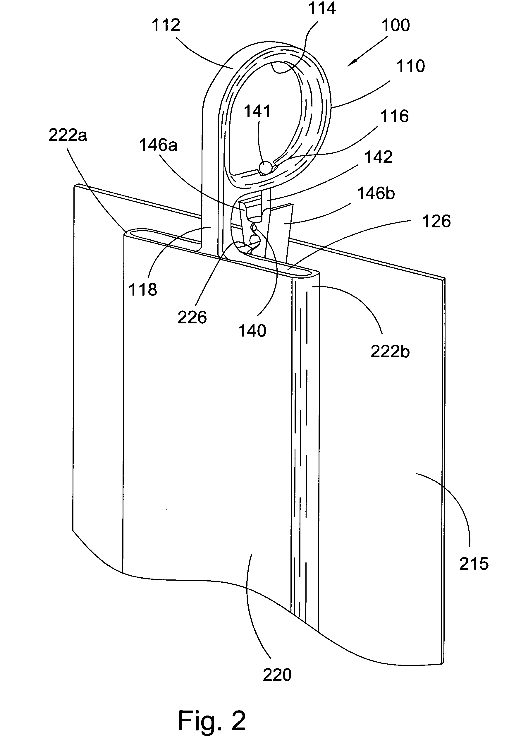
[0027]The following description is best understood in view FIGS. 1-7. FIG. 1 shows a front perspective view of drapery assembly 200 comprising drapery rod 210, which is preferably arranged substantially horizontally and secured proximate a vertical surface, such as a wall, a plurality of first embodiment drapery clip rings 100 slidably disposed around drapery rod 210, and drapery 215 hanging from the plurality of clip rings 100. Drapery 210 rod may be any suitable rod operatively arranged to hang drapery thereon. Drapery 215 may be made of any suitable material, such as textile, fabrics, plastics, or the like, and comprises a plurality of box pleats 220 formed via the plurality of drapery clip rings 100. The plurality of clip rings 100 is operatively arranged to support the weight of drapery 215 as described infra.

[0028]Drapery clip ring 100 comprises ring 110 having outer surface 112, gripping means 140 connected to and extending away from ring 110, and pleat endoskeleton 120 conne...

second embodiment

[0034]FIGS. 8-11 show second embodiment drapery clip ring 300. Drapery clip ring 300 comprises ring 310 having outer surface 312, gripping means 340 connected to and extending away from ring 310, and pleat endoskeleton 320 connected to and extending away from ring 310 and arranged proximate gripping means 340. Preferably, pleat endoskeleton 320 is arranged substantially in front of gripping means 340. Ring 310 further includes inner surface 314, which preferably comprises recess 316, and through-bore 317, which extends from inner surface 314 to outer surface 312. Ring 310 is arranged to slidably receive rod 210 therethrough. In a preferred embodiment, pleat endoskeleton 320 is connected to outer surface 312 via member 318, which may be a substantially straight extension tangentially connected to ring 310. In this embodiment, ring 310 is substantially circular.

[0035]Pleat endoskeleton 320 comprises back surface 330 and front surface 322, which is preferably substantially planar and b...


PUM


Abstract

A drapery clip ring for hanging drapery on a drapery rod, the drapery clip ring including a ring arranged to receive the drapery rod therethrough, a gripping means connected to and extending away from the ring, and a pleat endoskeleton connected to and extending away from the ring, the pleat endoskeleton being arranged proximate the gripping means, wherein the pleat endoskeleton is adapted to provide an internal framework of a pleat formed in the drapery, and the gripping means is operatively arranged to secure the pleat formed in the drapery.

Description

FIELD OF THE INVENTION[0001]The invention broadly relates to drapery hardware. More particularly, the invention relates to drapery clip rings and, even more particularly, to pleat-forming drapery clip rings.BACKGROUND OF THE INVENTION[0002]Clip rings are well known drapery hardware used for hanging drapery and curtains. A clip ring generally comprises a simple ring with a clip extending therefrom. The ring is arranged to fit around a drapery rod such that it is easily slidable along the length thereof. The clip is arranged to hang below the rod and securely grip a portion of the fabric of the drapery.[0003]Generally, a plurality of clip rings, arranged in succession along the length of the rod, is used to hang the drapery. As the clip rings are easily slidable along the rod, a user may easily position the drapery hanging therefrom at desired locations along the rod. When the drapery is gathered together, its fabric tends to bunch and fold, especially near the upper portion of its fa...

Claims


Application Information

Patent Timeline
IPC IPC(8): A47H13/02
CPCY10T24/51A47H13/16
Inventor LORENZATTI, LUCIANO
Owner UMBRA
Learn More