
Image coding apparatus, image coding method, integrated circuit, and camera

a technology of image coding and coding method, which is applied in the direction of signal generator with optical-mechanical scanning, color television with bandwidth reduction, etc., can solve the problems of reducing image quality and coding efficiency in other cases, and reducing image quality and coding efficiency. , to achieve the effect of improving image quality and coding efficiency, reducing computation amount, and accelerating the process

Active Publication Date: 2010-02-04
PANASONIC CORP
View PDF3 Cites 14 Cited by
  • Summary
  • Abstract
  • Description
  • Claims
  • Application Information

AI Technical Summary

Benefits of technology

[0016]Furthermore, the weighted prediction contributes to the improvement of the coding efficiency when the luminance values are changing in the entire image. However, the weighted prediction could possibly reduce the image quality and the coding efficiency in other cases. For this reason, as with the technique disclosed in Patent Reference 1, there is a case where the image quality and coding efficiency is reduced, since merely detecting the change in the luminance value is not sufficient.
[0038]According to the present invention, it is possible to improve the image quality and the coding efficiency while reducing the computation amount, and accelerating the process, and reducing the consumption electricity in the image compression-coding process.Further Information about Technical Background to This Application

Problems solved by technology

However, there is a problem where the technique disclosed in Patent Reference 1 reduces the image quality and the coding efficiency.
However, the weighted prediction could possibly reduce the image quality and the coding efficiency in other cases.
For this reason, as with the technique disclosed in Patent Reference 1, there is a case where the image quality and coding efficiency is reduced, since merely detecting the change in the luminance value is not sufficient.
However, this method increases the process amount necessary for coding, and causes a problem such as the increase in circuit scale and consumption electricity.

Method used


Image

  • Image coding apparatus, image coding method, integrated circuit, and camera
  • Image coding apparatus, image coding method, integrated circuit, and camera
  • Image coding apparatus, image coding method, integrated circuit, and camera

Examples


first embodiment

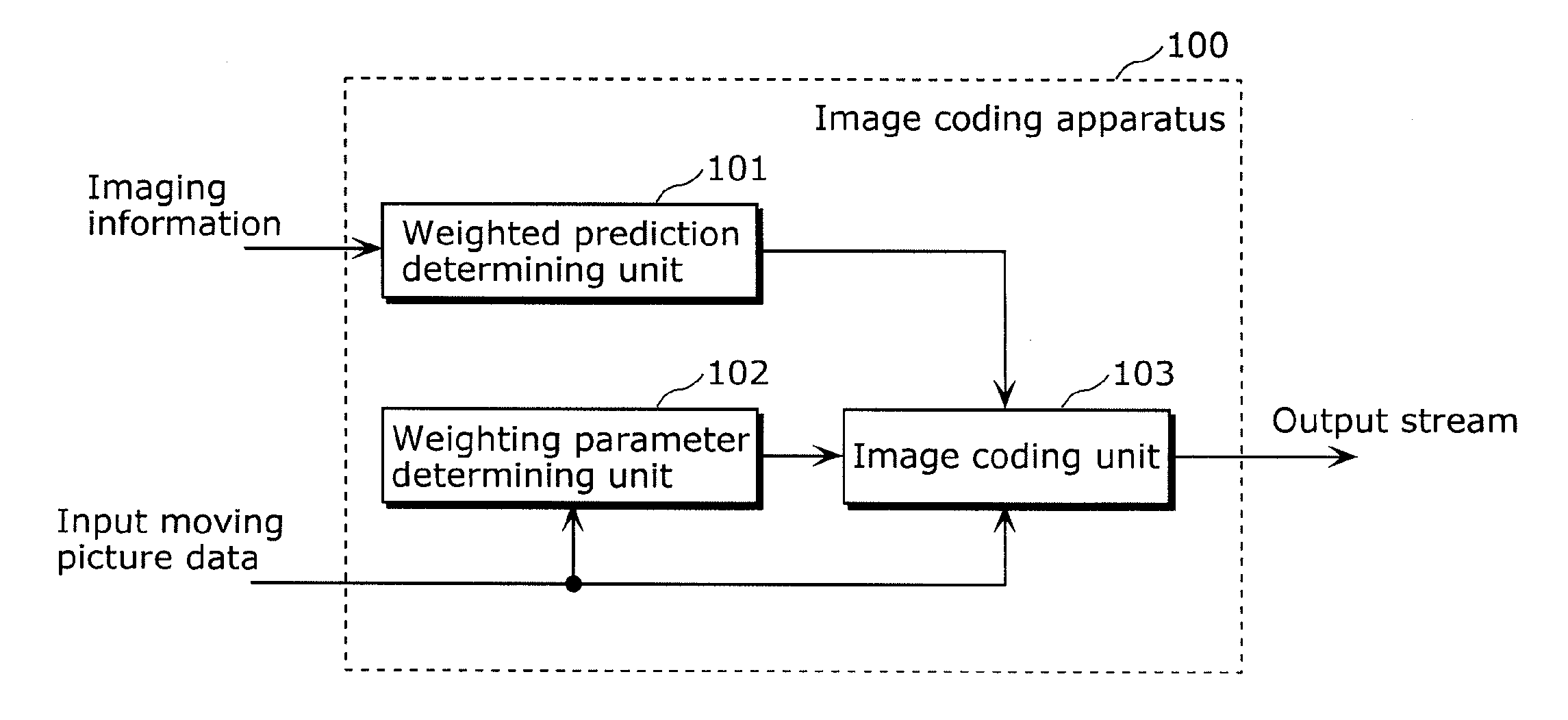
[0055]The image coding apparatus according to the first embodiment includes: a determining unit which determines whether or not the current image to be coded is included in, among the moving picture data, a picture group which is a group of successive pictures and indicates motion equal to or larger than a predetermined amount of motion; and a predicted image generating unit which generates a predicted image by performing motion compensation without weighted prediction when it is determined that the current image to be coded is included in the picture group or motion compensation with the weighted prediction when it is determined that the current image to be coded is not included in the picture group.

[0056]FIG. 1 is a block diagram showing an example of the structure of an image coding apparatus 100 according to the first embodiment. As shown in FIG. 1 the input moving picture data which includes multiple pictures and imaging information which is additional information on the input ...

second embodiment

[0114]The image coding apparatus according to the second embodiment determines that the current image to be coded an image with motion when a characteristic amount calculated based on the current image to be coded and a previous image that is to be coded is equal to or larger than a predetermined threshold, and determines that the current image to be coded is not with motion when the characteristic amount is smaller than the threshold. As described above, the image coding apparatus according to the second embodiment determines whether or not the current image to be coded is with motion to select whether or not the weighted prediction is performed based on the determination result.

[0115]FIG. 6 is a block diagram showing an example of the structure of an image coding apparatus 300 according to the second embodiment.

[0116]As shown in FIG. 6, the image coding apparatus 300 includes a weighted prediction determining unit 301, the weighted parameter determining unit 102, and the image cod...

third embodiment

[0128]The image coding apparatus according to the third embodiment determines that the current image to be coded is an image with motion when a characteristic amount calculated based on a previously coded image is equal to or larger than a predetermined threshold, and determines that the current image to be coded is not an image with motion when the characteristic amount is smaller than the threshold. As described above, the image coding apparatus according to the third embodiment selects whether or not the weighted prediction is performed based on the determination result whether or not the previously coded image is with motion.

[0129]FIG. 8 is a block diagram showing an example of the structure of the image coding apparatus 400 according to the third embodiment.

[0130]As shown in FIG. 8, the image coding apparatus 400 includes a weighted prediction determining unit 401, the weighting parameter determining unit 102, and an image coding unit 403. The weighting parameter determining un...


PUM


Abstract

An image coding apparatus which compression-codes moving picture data including a current image to be coded, the image coding apparatus including an accumulating unit which accumulates a reference image, a predicted image generating unit which generates a predicted image of the current image to be coded, based on the reference image accumulated in the accumulating unit, by performing motion compensation with weighted prediction or motion compensation without the weighted prediction, the weighted prediction being a process of adding a predetermined offset value to a pixel value of the reference image, a coding unit which codes a difference between the predicted image generated by the predicted image generating unit and the current image to be coded, and a determining unit which determines whether or not the current image to be coded is included in, among the moving picture data, a picture group which is a group of successive pictures and indicates motion equal to or larger than a predetermined amount of motion, in which the predicted image generating unit generates the predicted image by performing the motion compensation without the weighted prediction when the determining unit determines that the current image to be coded is included in the picture group, and to generate the predicted image by performing the motion compensation with the weighted prediction when it is determined that the current image to be coded is not included in the picture group.

Description

BACKGROUND OF THE INVENTION[0001](1) Field of the Invention[0002]The present invention relates to an image coding apparatus which compression-codes images and records the compression-coded images on storage media such as optical discs, magnetic disks, and flash memories and others, and an image coding method. More particularly, the present invention relates to an image coding apparatus which performs the compression-coding in the MPEG-4 AVC / H.264 compression-coding standard, an image coding method, an image coding integrated circuit, and a camera.[0003](2) Description of the Related Art[0004]Along with the progress in the digital video technology, there has been progress in techniques for compression-coding the digital video data in response to the increasing the data amount. The compression-coding technology specialized for the video data making use of the video data shows the progress.[0005]Furthermore, improvement in the processing capacity of the information processing devices s...

Claims


Application Information

Patent Timeline
IPC IPC(8): H04N5/228H04N7/26H04N19/105H04N19/50H04N19/12H04N19/134H04N19/136H04N19/137H04N19/139H04N19/159H04N19/16H04N19/189H04N19/196H04N19/42H04N19/423H04N19/503H04N19/51H04N19/513H04N19/523H04N19/593H04N19/61H04N19/625H04N19/80H04N19/85H04N19/91
CPCH04N19/105H04N19/139H04N19/573H04N19/174H04N19/16
Inventor MARUYAMA, YUKI
Owner PANASONIC CORP
Learn More