Decorative member and process for manufacturing the same

a technology of decorative components and manufacturing steps, applied in the field of decorative components, can solve the problems of troublesome manufacturing steps, difficult to form the second decorated layer b>503/b> highly accurately by means of application, complicated manufacturing steps, etc., and achieves high-accuracy formability of the second decorated layer, good elongation deformability, and good decorative

Active Publication Date: 2010-02-04
TOYODA GOSEI CO LTD
View PDF9 Cites 33 Cited by
  • Summary
  • Abstract
  • Description
  • Claims
  • Application Information

AI Technical Summary

Benefits of technology

[0049]Moreover, it is possible to highly accurately shape the second decorated layer into a configuration, which coincides with or is die-symmetric to the first decorated layer but also coincides with or is die-symmetric to the rear surface of the transparent layer, because the resinous layer, an element of the second decorated layer, is made from at least one resinous material that is selected from the group consisting of polyurethane, polymethylmethacrylate, acrylonitrile-butadiene-styrene copolymer, polycarbonate, polyethylene terephthalate, polypropylene, polyethylene and fluorocarbon resin. The highly-accurate formability of the second decorated layer results from the fact that films, which comprise these resinous materials, exhibit good elongation deformability.
[0050]For the reasons stated above, the process for manufacturing decorative member according to the present invention that is further provided with above-described optional feature (1) enables manufacturers to manufacture decorative members that are good in terms of decorativeness. Thus, the decorative member according to the present invention that further comprises above-described optional feature (6) can demonstrate upgraded decorativeness.
[0051]The process for manufacturing decorative member according to the present invention that is further provided with above-described optional feature (2) makes it possible to optimize the before-lamination thicknesses of the vapor-deposited metallic layer and resinous layer. Accordingly, it is possible to let the resinous layer undergo elongation deformation fully while inhibiting the resinous layer from being broken, ruptured or fractured. Consequently, manufactures can manufacture decorated members that are much better in terms of decorativeness, using the present manufacturing process that is provided with above-described optional feature (2).
[0052]The process for manufacturing decorative member according to the present invention that is further provided with above-described optional feature (3) makes it possible to position the first decorated layer with ease and with high accuracy, because the first decorated layer is formed onto the transparent layer's rear surface by means of two-color molding partially on at least a part of the indent-free portions. Moreover, the present manufacturing process makes it possible to inhibit the first decorated layer from coming off from the transparent layer, because forming the first decorated layer onto the transparent layer's rear surface by means of two-color molding makes it possible to integrate the transparent layer and the first decorated layer highly reliably. In addition, the first decorated layer's rear surface comprises the groove that is connected to or communicated with one of the indented portions of the transparent layer's rear surface. Accordingly, gas that remains between the transparent layer and the second decorated layer can move to the inside of the groove. That is, the gas is less likely to remain between the second decorated layer and the transparent layer so that the second decorated layer can come in press contact with the transparent layer firmly. Consequently, the present manufacturing process makes it possible to keep down the deterioration of decorated members' decorativeness, deterioration which arises from the gas that has remained between the transparent layer and the second decorated layer. All in all, the present manufacturing process that is further provided with above-described optional feature (3) makes it possible to manufacture decorative members that are much better in terms of decorativeness. Therefore, the decorative member according to the present invention that further comprises above-described optional feature (7) can demonstrate decorativeness that is upgraded furthermore.
[0053]The process for manufacturing decorative member according to the present invention that is further provided with above-described optional feature (4) makes it possible to discharge gas that has gone inside the groove that is disposed in the first decorated layer's rear surface to the outside of resultant decorative members. Accordingly, the present manufacturing process that is further provided with above-described optional feature (4) enables manufacturers to manufacture the decorative member according to the present invention from which gas that remains between the transparent layer and the second decorated layer has been removed with high reliability. Consequently, the present manufacturing process that is further provided with above-described optional feature (4) enables manufacturers to manufacture decorative members that demonstrate much better decorativeness. Thus, the decorative member according to the present invention that further comprises above-described optional feature (7) is upgraded furthermore in terms of decorativeness.
[0054]The process for manufacturing decorative member according to the present invention that is further provided with above-described optional feature (5) enables manufacturers to manufacture decorative members that demonstrate much better decorativeness in a fashion similar to that of the present manufacturing process that is further provided with above-described optional feature (4), but more reliably than it does.

Problems solved by technology

Accordingly, there arises such a problem that the manufacturing steps for completing decorated member might have become complicated.
However, since the transparent layer 501 takes on an irregular configuration, it might be difficult to form the second decorated layers 503 highly accurately by means of application, depending on positions at which the second decorated layers 503 are formed.
Moreover, such a first method might have required troublesome manufacturing steps in order to form the second decorated layers 503 with high accuracy by means of application.
To put it differently, the laminating method might not allow a manufacturing worker or robot to position the break or separation lines 570 highly accurately.
As a result, completed decorative members might exhibit deteriorated decorativeness.

Method used


Image

  • Decorative member and process for manufacturing the same
  • Decorative member and process for manufacturing the same
  • Decorative member and process for manufacturing the same

Examples


examples

[0078]Hereinafter, decorative members according to the present invention, and processes for manufacturing the same will be described with reference to specific examples.

example no.1

Example No. 1

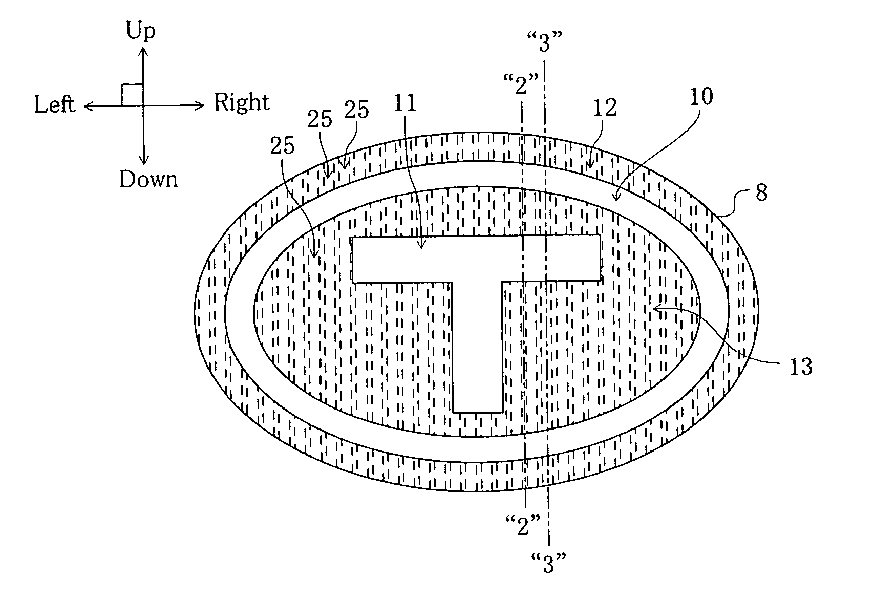
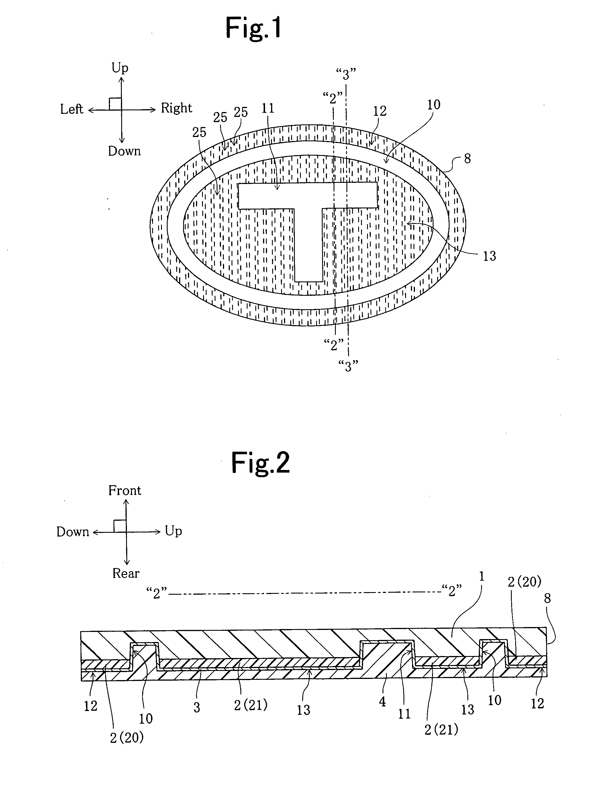
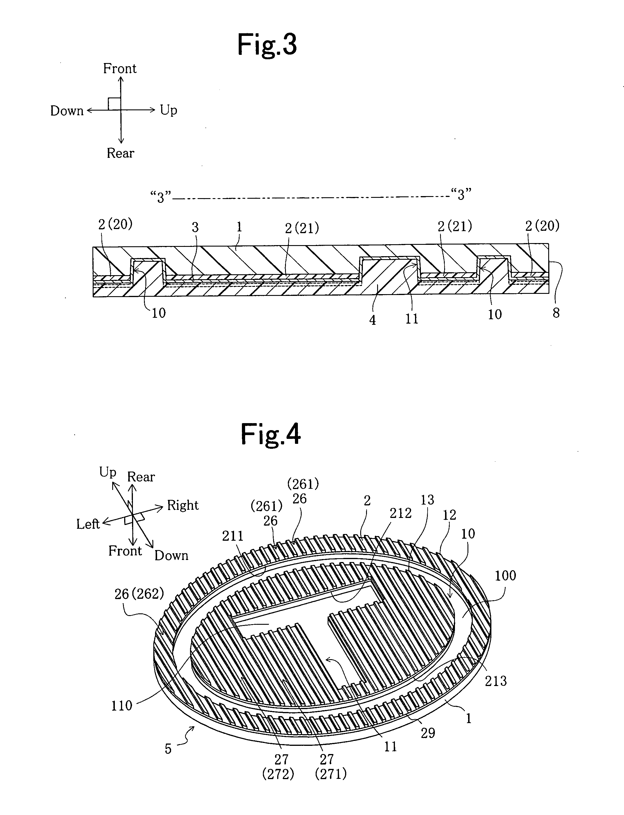
[0079]A decorative member according to Example No. 1 of the present invention is directed to one of embodiments of the present invention in which the present decorative member is applied to making an emblem for automobile. Moreover, the present decorative member according to Example No. 1 is manufactured by a process for manufacturing decorative member according to the present invention that is further provided with above-described optional features (1) through (5). In addition, the present decorative member according to Example No. 1 further comprises above-described optional features (6) through (8). FIG. 1 shows the present decorative member according to Example No. 1 schematically in a front-view diagram. FIG. 2 shows the present decorative member according to Example No. 1 schematically in a cross-sectional diagram that is taken along the imaginary chain double-dashed line “2”-“2” designated in FIG. 1. FIG. 3 shows the present decorative member according to Example...

example no.2

Example No. 2

[0106]A decorative member according to Example No. 2 of the present invention comprises the same constituent elements as those of the present decorative member according to Example No. 1, except that the first decorated layer is formed only on the bottom surfaces of the inner and outer indented portions of the transparent layer, and that the first decorated layer is free from the grooves that are connected to or communicated with the inner and outer indented portions. Moreover, the present decorative member according to Example No. 2 is manufactured by a process for manufacturing decorative member according to the present invention that is further provided with above-described optional features (1) and (2). In addition, the present decorative member according to Example No. 2 further comprises above-described optional feature (6). FIG. 10 shows the present decorative member according to Example No. 2 schematically in a cross-sectional diagram. In the drawing, the presen...


PUM

PropertyMeasurementUnit
thicknessaaaaaaaaaa
thicknessaaaaaaaaaa
thicknessaaaaaaaaaa

Abstract

A decorative member includes a transparent layer, a first decorated layer, and a second decorated layer. The first decorated layer is disposed on the transparent layer's rear surface. The second decorated layer is disposed on the transparent layer's rear surface. The transparent layer's rear surface has an irregular configuration that includes indented portions and indent-free portions. The indented portions dent toward the transparent layer's front surface. The indent-free portions protrude toward the transparent layer's rear surface. The first decorated layer is disposed directly on the rear surface of the transparent layer partially. The second decorated layer is made of a film that includes resin, and is laminated on the first decorated layer and on the transparent layer's rear surface entirely.

Description

INCORPORATION BY REFERENCE[0001]The present invention is based on Japanese Patent Application No. 2008-196,459, filed on Jul. 30, 2008, the entire contents of which are incorporated herein by reference.BACKGROUND OF THE INVENTION[0002]1. Field of the Invention[0003]The present invention relates to a decorative member that displays predetermined design or decoration stereoscopically or three-dimensionally, and to a process for manufacturing the same.[0004]2. Description of the Related Art[0005]Decorative members that display predetermined decorations three-dimensionally have been known. This type of decorative members (hereinafter simply referred to as “decorative members”) has been used in emblems and electromagnetic-wave transmissive covers for vehicle. In general, such a decorative member comprises a transparent layer, and a decoration layer that is disposed on the rear surface of the transparent layer. The rear surface of the transparent layer is formed as an irregular configurat...

Claims


Application Information

Patent Timeline
Patent Type & Authority Applications(United States)
IPC IPC(8): B32B3/30B32B15/08B32B37/02
CPCB32B37/02B32B38/06B32B2037/243B32B2038/0092B32B2309/105Y10T428/24521B44C3/02B44F1/045Y10T156/1039Y10T428/24545B32B2451/00G01S7/03G01S2013/93271H01Q1/3233H01Q1/42
Inventor FUJII, TETSUYATOTANI, CHIHARUIDO, TAKAYASU
Owner TOYODA GOSEI CO LTD
Why Eureka
Try Eureka