Catholyte heat recovery evaporator and method of use

a heat recovery evaporator and catholyte technology, applied in the direction of manufacturing tools, alkali metal hydroxides, sustainable manufacturing/processing, etc., can solve the problem that the concentration of aqueous caustic alkali products created by the electrolytic cell is normally not high enough to meet customer demands or be used efficiently in other processes, and the method disclosed will not work as described, etc., to achieve the effect of not being economical to sell

Active Publication Date: 2010-02-11
WESTLAKE VINYL CORP
View PDF14 Cites 6 Cited by
  • Summary
  • Abstract
  • Description
  • Claims
  • Application Information

AI Technical Summary

Benefits of technology

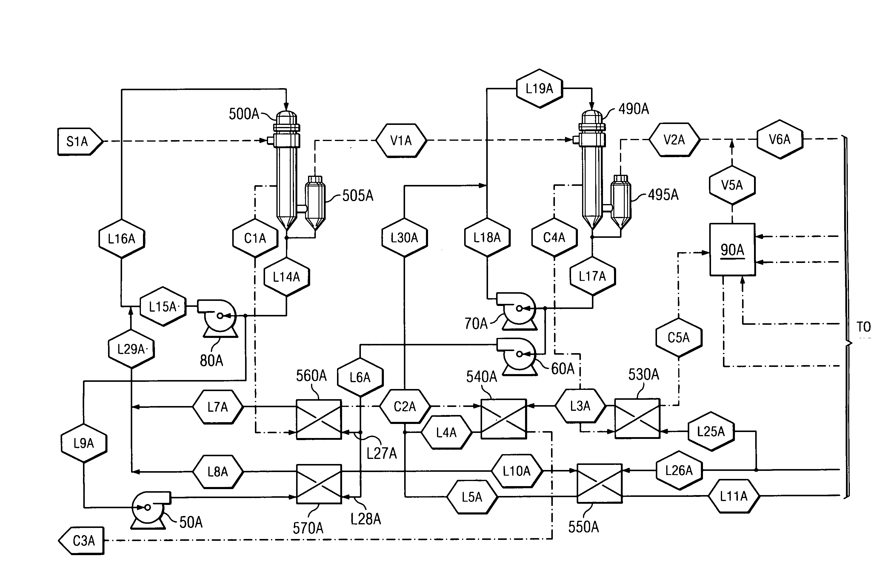
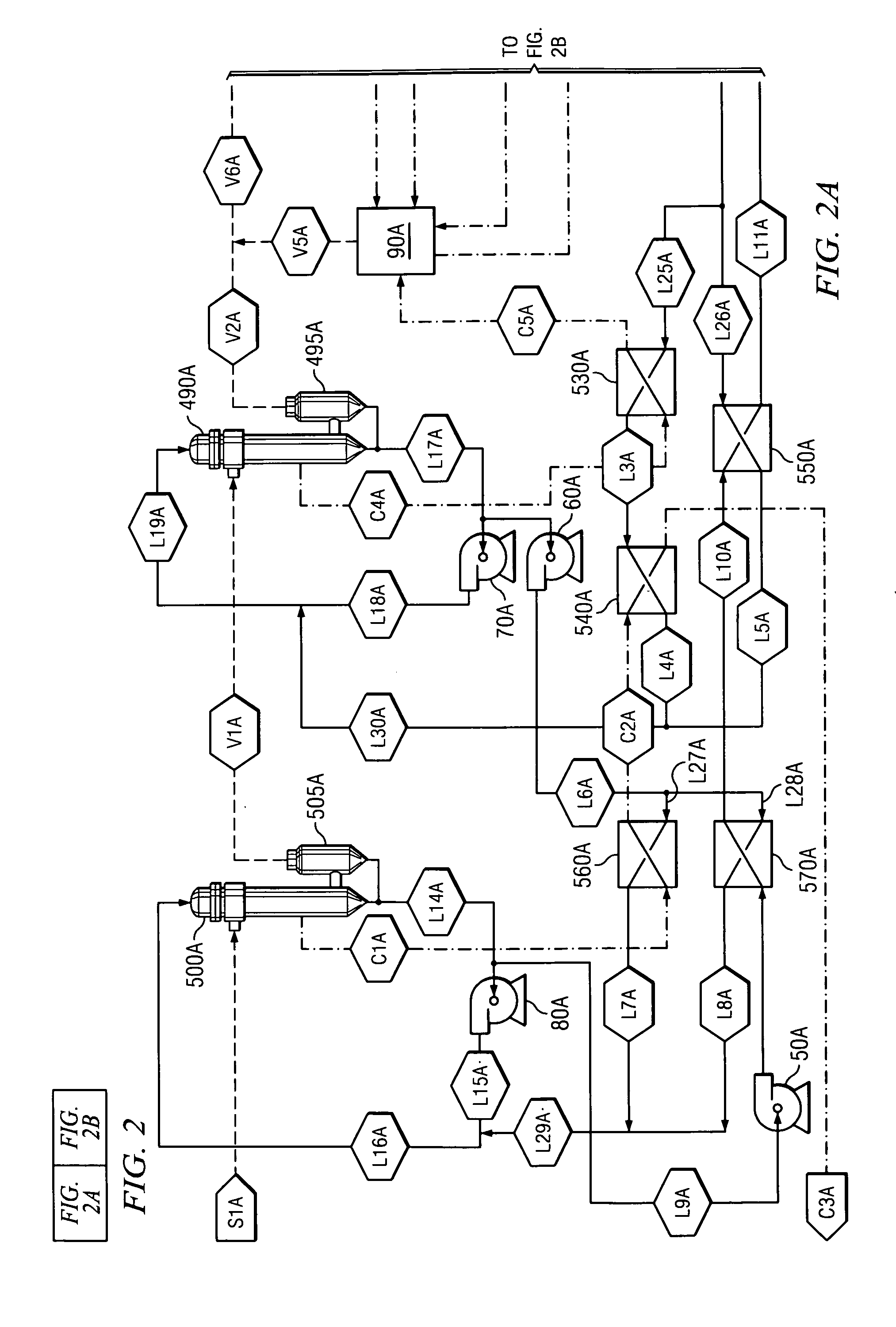
[0026]By recovering heat from the circulation line of the catholyte back to the cell, and the condensate lines from the effects, heating costs for the entire process are reduced. Further, by adding the catholyte heat recovery evaporation to an existing evaporator system, the amount of evaporation needed from each effect to reach the desired concentration is reduced, thereby increasing the potential to increase production when compared to the system without the catholyte heat recovery evaporator step.
[0027]In another embodiment, the catholyte heat recovery evaporator step is prior to the third effect. The catholyte to be concentrated enters a flash chamber which reduces the boiling temperature as the pressure is reduced allowing vapor to be removed and is further heated by a circulation line for the flash chamber that is heated by the catholyte circulating back to the membrane cell. With this configuration, the potential to increase production in an existing evaporator system is more difficult because additional heat transfer area must be added because of the increase in boiling point rise in all effects. This embodiment would be most beneficial if retrofitting an existing plant where the evaporation portion of the process is not located close to the cells.

Problems solved by technology

However, the concentration of the aqueous caustic alkali products created by the electrolytic cells is normally not high enough to meet customer demands or to be used efficiently in other processes.
However, the method disclosed will not work as described and cannot be easily modified without undue experimentation.
There are several reasons why the design disclosed by Kazihara is unworkable or impracticable.
Specifically, the circulated catholyte flow rate is excessive, the barometric condenser is incorrectly designed, and the catholyte heat exchanger is marginally designed.
First, the recirculated catholyte flow rate is excessive.
The high circulated catholyte rate specified by the Kazihara design is impracticable since this flow is not acceptable for current cell technology.
Second, the barometric condenser is inadequately designed.
Kazihara has either specified an incorrect Boiling Point Rise or has not allowed for a sufficient minimum temperature driving force for heat transfer for the barometric condenser.
Either the Boiling Point Rise has been incorrectly calculated or an inadequate temperature driving force has been specified.
), the design disclosed by Kazihara is unworkable in practice.
A catholyte heat exchanger designed with a ΔT smaller than 10° F. tends to be excessively large and also difficult to operate.
In summary, this is an unworkable design which suffers from three major problems.
Furthermore, any changes to fix one of these problems makes the other problems worse.
First, current state of the art electrolytic cells do not operate above atmospheric pressure.
Second, the disclosure only allows for the NaOH to be concentrated to 43% NaOH which is not economical to be sold as a product due to transportation and handling considerations.
Third, the procedure disclosed will not function properly or give the desired results if the cell pressure is not higher than atmospheric pressure.

Method used


Image

  • Catholyte heat recovery evaporator and method of use
  • Catholyte heat recovery evaporator and method of use
  • Catholyte heat recovery evaporator and method of use

Examples


Embodiment Construction

[0034]One way that aqueous alkali and aqueous caustic alkali are produced is through the use of cell membranes. The preferred feed materials to electrolytic cells include KCl (potassium chloride) producing KOH (also known as caustic potash) and NaCl (sodium chloride) producing caustic soda. Since NaCl is the most preferred feed material, caustic soda will be used to describe the method of use for the invention; however, other alkalis and caustic alkalis may be substituted. Other alkali metals include: lithium, rubidium, cesium, and francium.

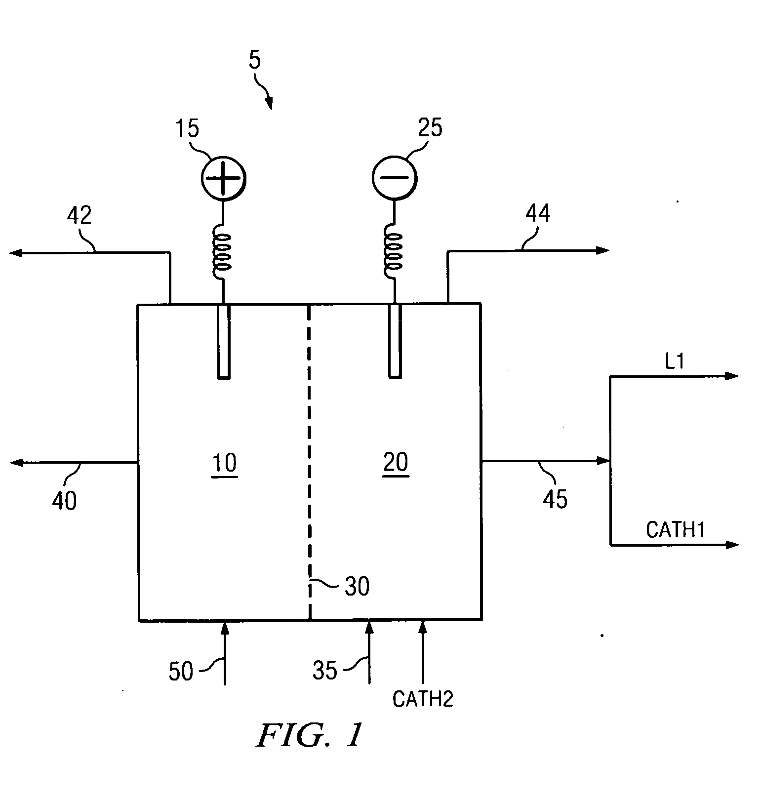
[0035]The creation of caustic soda through use of cell membranes is known in the art as discussed in relation to FIG. 1. Due to the electric current passing through electrolytic cell 5, the temperature of the contents in anode chamber 10 and cathode chamber 20 are elevated.

[0036]The catholyte removed from cathode chamber 20 is split into a concentration stream and circulation stream. The concentration stream flows through line L1. The circulation...


PUM

PropertyMeasurementUnit
boiling pointaaaaaaaaaa

Abstract

A method for concentrating an aqueous caustic alkali produced by a membrane cell process by using a single or multiple effect evaporator system in which the vapor flows in a counter direction to the aqueous caustic alkali flow and the heat recovered from the catholyte circulation line is used as part of the concentration process. In one embodiment, a catholyte heat recovery heat exchanger and evaporation chamber are located after the last effect of a multiple effect evaporator system. In another embodiment, the catholyte heat recovery heat exchanger and evaporation chamber are located prior to the single or multiple effect evaporator system. In yet another embodiment, the catholyte heat recovery process is used in conjunction with additional heat exchanger processes to further concentrate the final product as desired.

Description

FIELD OF THE INVENTION[0001]The present invention relates to a method of recovering heat created as a by-product of one process for use as a heat source in another process. One specific example of the present invention relates to a method of recovering heat from the catholyte circulation stream from a membrane cell process to be used to reduce heating utility consumption in a multiple effect evaporation step.BACKGROUND OF THE INVENTION[0002]Electrolytic cells and cell membrane technologies have existed for many years. The function of electrolytic cells is to create aqueous caustic alkali products, such as caustic soda (NaOH).[0003]The method by which the electrolytic cell creates aqueous caustic alkali products, specifically caustic soda, is as follows. Brine (or salt water) is used to create caustic soda, hydrogen gas, and chlorine gas. Referring to FIG. 1, electrolytic cell 5 has anode 15 and cathode 25 and cell membrane 30 between anode 15 and cathode 25. The use of cell membrane...

Claims


Application Information

Patent Timeline
Patent Type & AuthorityApplications(United States)
IPC IPC(8): C25B1/16C25B9/00
CPCC01D1/40C01D1/42C02F1/048C25B1/16B01D1/26C25B15/08C01D1/04C25B1/46Y02P20/10Y02P20/50Y02P70/10
InventorDAVIS, ANTHONY B.YOHE, THOMAS H.DUNN, RUSSELL F.
OwnerWESTLAKE VINYL CORP