
Fall restraint equipment components and method for manufacturing the same

a technology for restraint equipment and components, which is applied in the direction of manufacturing tools, transportation and packaging, and passenger handling apparatus, etc., can solve the problems of increasing the cost associated with manufacturing the end product, time-consuming and costly, and manufacturing a handrail in this manner,

Active Publication Date: 2010-02-11
SAFERACK
View PDF47 Cites 15 Cited by
  • Summary
  • Abstract
  • Description
  • Claims
  • Application Information

AI Technical Summary

Problems solved by technology

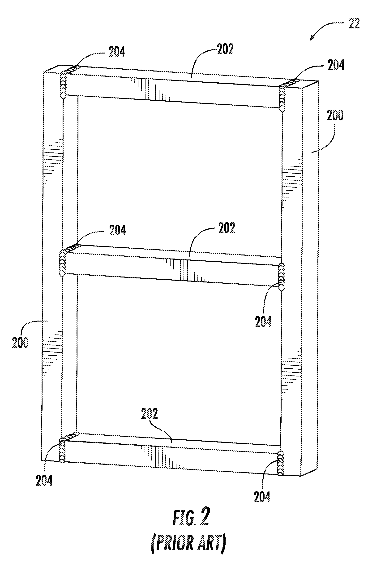
Manufacturing a handrail, such as handrail 22, in this manner is both time-consuming and costly.
Variances greater than an acceptable level render the smaller pieces unusable, which are typically discarded as they often are unusable in another product once they have been drilled or cut.
Additionally, if other parts cannot be cut or drilled from the remaining portions of the stock materials, they too are discarded.
This also increases the costs associated with manufacturing the end product, such as handrails 106.

Method used


Image

  • Fall restraint equipment components and method for manufacturing the same
  • Fall restraint equipment components and method for manufacturing the same
  • Fall restraint equipment components and method for manufacturing the same

Examples


Embodiment Construction

[0023]Reference will now be made in detail to presently preferred embodiments of the invention, one or more examples of which are illustrated in the accompanying drawings. Each example is provided by way of explanation of the invention, not limitation of the invention. In fact, it will be apparent to those skilled in the art that modifications and variations can be made in the present invention without departing from the scope or spirit thereof. For instance, features illustrated or described as part of one embodiment may be used on another embodiment to yield a still further embodiment. Thus, it is intended that the present invention covers such modifications and variations as come within the scope of the appended claims and their equivalents.

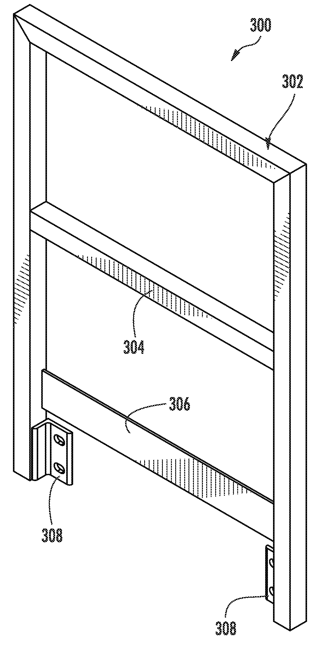
[0024]FIGS. 3 and 4 are perspective and front elevation views, respectively, of a handrail 300 that may be substituted for handrail 22 of the fall restraint equipment of FIG. 1. Handrail 300 comprises an outer rail 302, a midrail 304, and a to...


PUM


Abstract

A handrail or a swing gate for fall restraint equipment comprising an outer rail constructed from a single, continuous piece of tubular metal, a midrail constructed from a single, continuous piece of tubular metal, and a toeboard constructed from a single, continuous piece of sheet metal, where the outer rail is constructed to receive portions of the midrail and toeboard for an integral construction.

Description

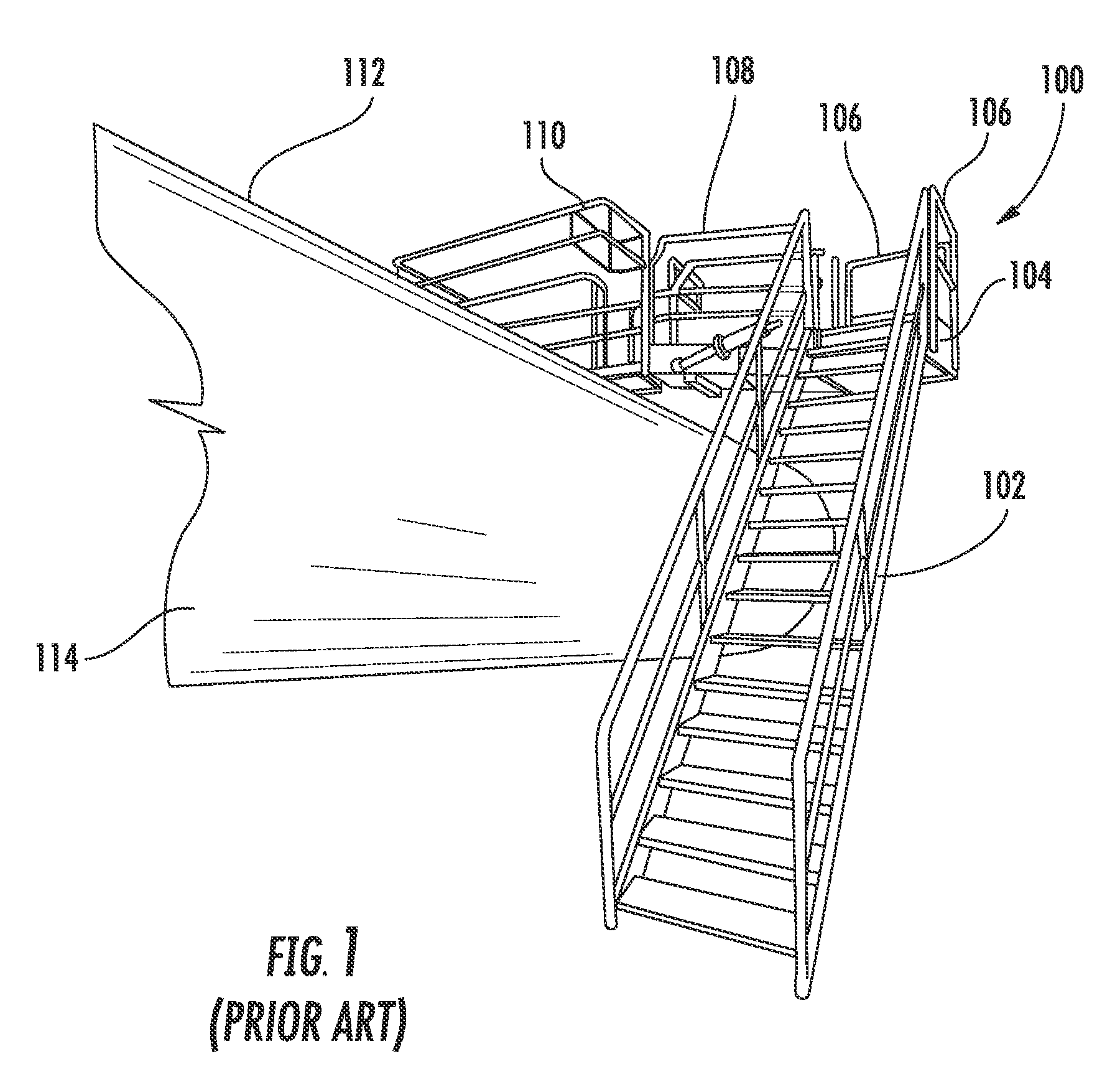
CLAIM OF PRIORITY[0001]The present application claims the benefit of the U.S. provisional patent application filed on Aug. 10, 2008 by Robert W. Honeycutt for COMPONENTS OF SAFETY EQUIPMENT AND METHODS FOR MANUFACTURING THE SAME (Ser. No. 61 / 087,732), the entire disclosure of which is hereby incorporated by reference as if set forth verbatim herein.FIELD OF THE INVENTION[0002]The present invention relates generally to fall restraint equipment components. More particularly, the present invention relates to handrails and swing gates for fall restraint equipment.BACKGROUND OF THE INVENTION[0003]FIG. 1 illustrates an example of fall restraint equipment 100 comprising a stairwell 102, a platform 104, handrails 106, and a gangway 108. Stairwell 102 ascends to platform 104, where gangway 108 is connected. An optional cage 110 may be connected to gangway 108 if desired. Handrails 106 are located on the sides of platform 104 that are not connected to either gangway 108 or stairwell 102 in or...

Claims


Application Information

Patent Timeline
IPC IPC(8): E04H17/16E04H17/14B23P13/04B23P11/00
CPCB63B27/14E04F11/112B21D39/06E04F11/04E04H17/14E04F11/00Y10T29/49826Y10T29/49936Y10T29/49947Y10T29/49996E04F11/181
Inventor HONEYCUTT, ROBERT W.
Owner SAFERACK
Learn More