Method and apparatus for repairing or replacing chordae tendinae

a technology of chordae tendinae and chordae tendinae, which is applied in the field of chordae tendinae replacement, repair or supplementation, can solve the problems of improper function dysfunction of any of these portions regurgitation of the mitral valve, so as to achieve the effect of optionally adjusting the length of the filamen

a technology of chordae tendinae and chordae tendinae, which is applied in the field of chordae tendinae replacement, repair or supplementation, can solve the problems of improper function dysfunction of any of these portions regurgitation of the mitral valve, so as to achieve the effect of optionally adjusting the length of the filamen

US20100042147A1Active Publication Date: 2010-02-18EDWARDS LIFESCIENCES CORP

Image

  • Method and apparatus for repairing or replacing chordae tendinae
  • Method and apparatus for repairing or replacing chordae tendinae
  • Method and apparatus for repairing or replacing chordae tendinae

Examples


Embodiment Construction

[0057]The present disclosure relates to methods and apparatuses for providing mitral valve chordal repair that permits the mitral valve leaflets to be attached to the papillary muscles or ventricular wall in a manner that is both minimally invasive and / or that permits chordal length adjustments.

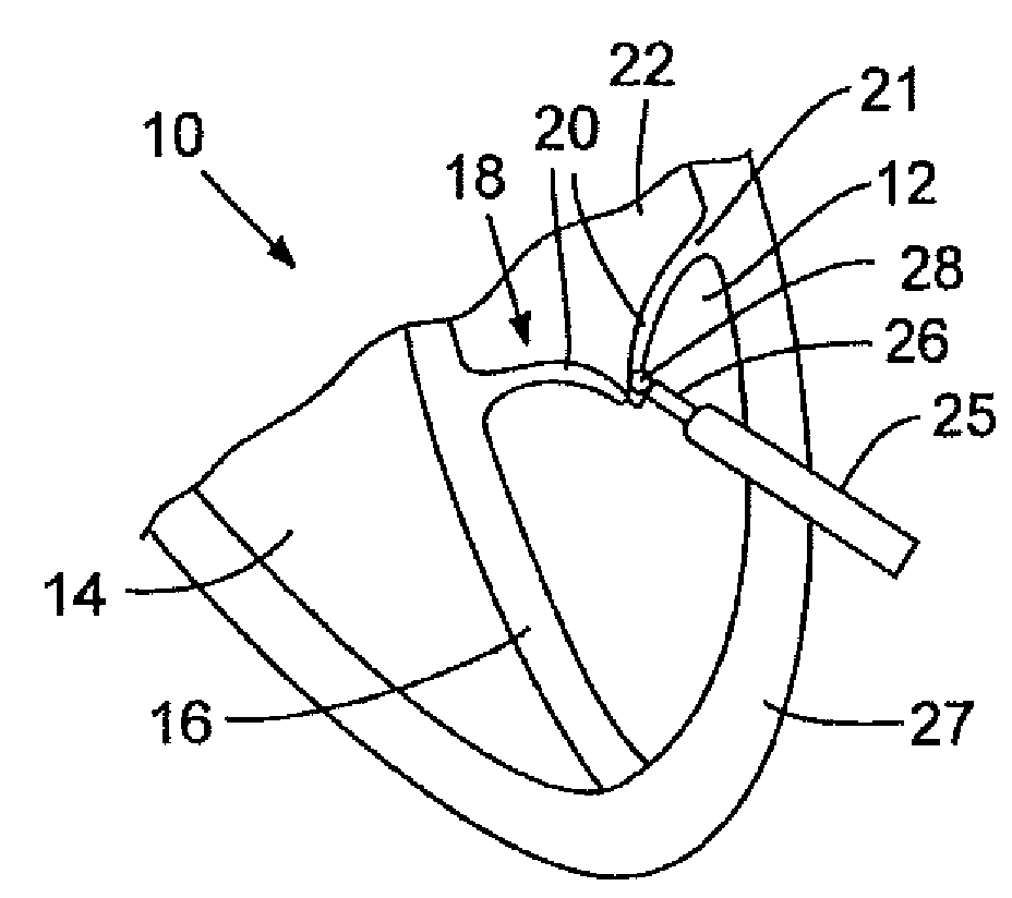
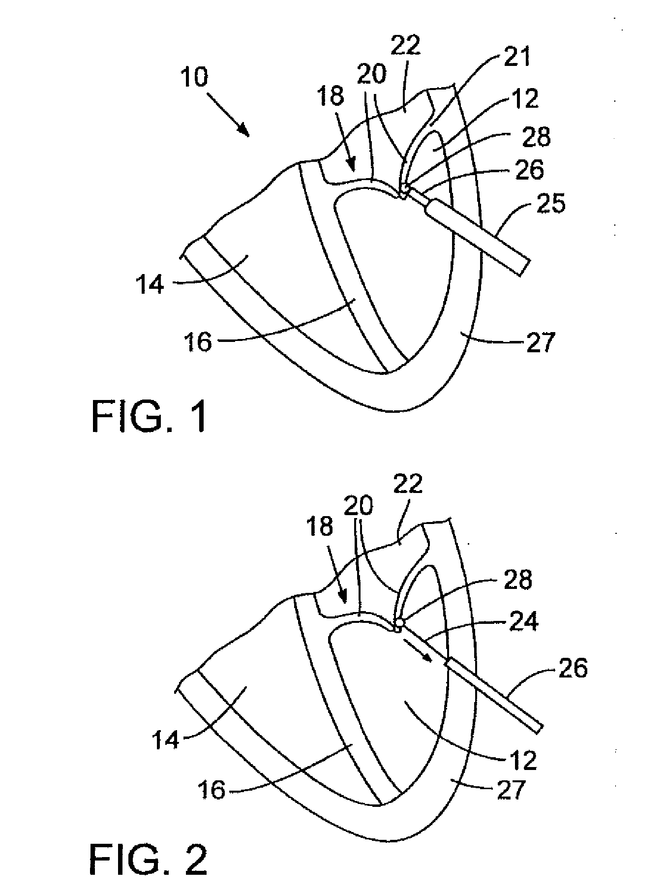
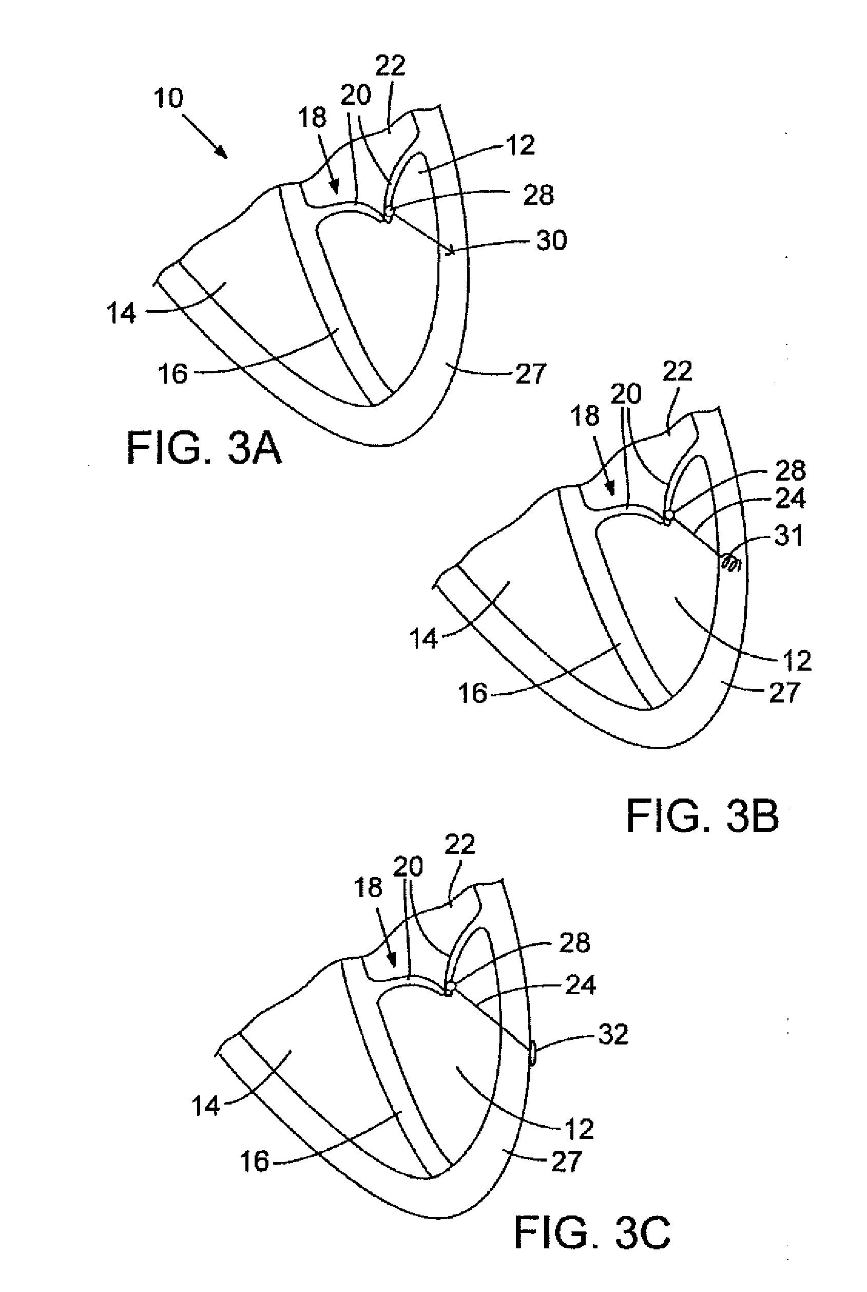
[0058]FIGS. 1-4 illustrate one embodiment of a method for mitral valve chordal repair that is minimally invasive and permits adjustment of the length of the artificial chordae. FIG. 1 depicts a schematic portion of a human heart 10. Heart 10 includes left ventricle 12, right ventricle 14, and septum 16. The mitral valve 18 includes valve leaflets 20, the mitral valve annulus 21, the papillary muscles (not shown), and the chordae tendineae (not shown). The chordae connect the valve leaflets to the papillary muscle in the left ventricle to prevent them from prolapsing into the left atrium 22. One or more filaments 24 can be attached to valve leaflets 20 in the event that the natural chordae hav...


PUM


Abstract

A method and apparatus for performing mitral valve chordal repair on a patient include attaching at least one filament to a mitral valve leaflet and to a papillary muscle. A first end of a filament can be attached to the mitral valve leaflet and the length of the filament can be adjusted by adjusting the tension of the filament in a catheter. The second end of the filament can be attached to an attachment site.

Description

BACKGROUND[0001]The present disclosure concerns methods and apparatuses for replacing, repairing, or supplementing chordae tendinae to improve or restore the connection of the mitral leaflets to the heart wall.DESCRIPTION OF THE RELATED ART[0002]Mitral regurgitation is a valvular heart disease that results in the abnormal leaking of blood through the mitral valve, from the left ventricle into the left atrium of the heart. The mitral valve includes valve leaflets and a mitral valve annulus that forms a ring around the valve leaflets. Chordae tendineae connect the valve leaflets to the papillary muscles, which tether the valve leaflets to the left ventricle and prevent them from prolapsing into the left atrium. Mitral regurgitation can result from the dysfunction of any of these portions of the mitral valve.[0003]In some patients with mitral regurgitation, the abnormal leakage of blood is caused, at least in part, from damaged chordae. The chordae can be, for example, elongated or tor...

Claims


Application Information

Patent Timeline
18 Feb 2010
Publication
US20100042147A1
IPC
A61B17/04; A61B19/00; A61F2/24
CPC
A61B17/0401; A61B17/0487; A61B2017/00243; A61B2017/00292; A61B2017/00783; A61F2/2463; A61B2017/0417; A61B2017/0441
Inventors
JANOVSKY, CHRIS; OLSON, CHRISTOPHER