Jig for selecting valve part number or joint part number

a valve or joint part technology, applied in the direction of identification means, instruments, mechanical digital computers, etc., can solve the problems of time and effort required for selecting a valve part number, difficult to recognize a selected condition or a selected part, and difficult for a user to select these valve or joint part numbers effectively

Inactive Publication Date: 2010-03-04
FUJIKIN INC
View PDF7 Cites 0 Cited by
  • Summary
  • Abstract
  • Description
  • Claims
  • Application Information

AI Technical Summary

Problems solved by technology

However, it was difficult for a user to select these valve or joint part numbers effectively.
For this reason, time and effort are required for selecting a valve part number after deciding the valve for use.
However, there were many problems with a jig for selecting a valve part number or a joint part number disclosed in Japanese Patent Publication No. 2005-164550.
In Example 1, as shown in FIG. 7, misalignment among the selected conditions or among the symbols resulting from simultaneous movement between the plurality of the condition selecting window (24) and the plurality of the symbol selecting window (25) makes it difficult to recognize a selected condition or a selected part number in a moment, and may further cause a misreading for them.
Also the example shown in FIG. 7 does not only expose desired conditions and desired symbols from the (24) and the (25) but also unrelated conditions and symbols, which also result in a potential misleading.
Thus, it is troublesome to change the part number.
There is also a problem of misreading caused by displacement of the sliding gauge (21) before reading.
This causes a big friction between the sliding gauge and the base body at every condition or symbol of the sliding gauge when the sliding gauge is slid.

Method used


Image

  • Jig for selecting valve part number or joint part number
  • Jig for selecting valve part number or joint part number
  • Jig for selecting valve part number or joint part number

Examples


Embodiment Construction

[0050]In one embodiment of the present invention, a selection of a joint part number is described, however, the present invention is also acceptable for a selection of a valve part number.

[0051]Note that the term “a joint part number” means “a combination of a number or a symbol for identifying a joint” which is defined for a joint by those skilled in the art such as a joint manufacturer.

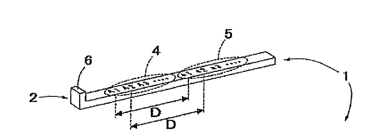
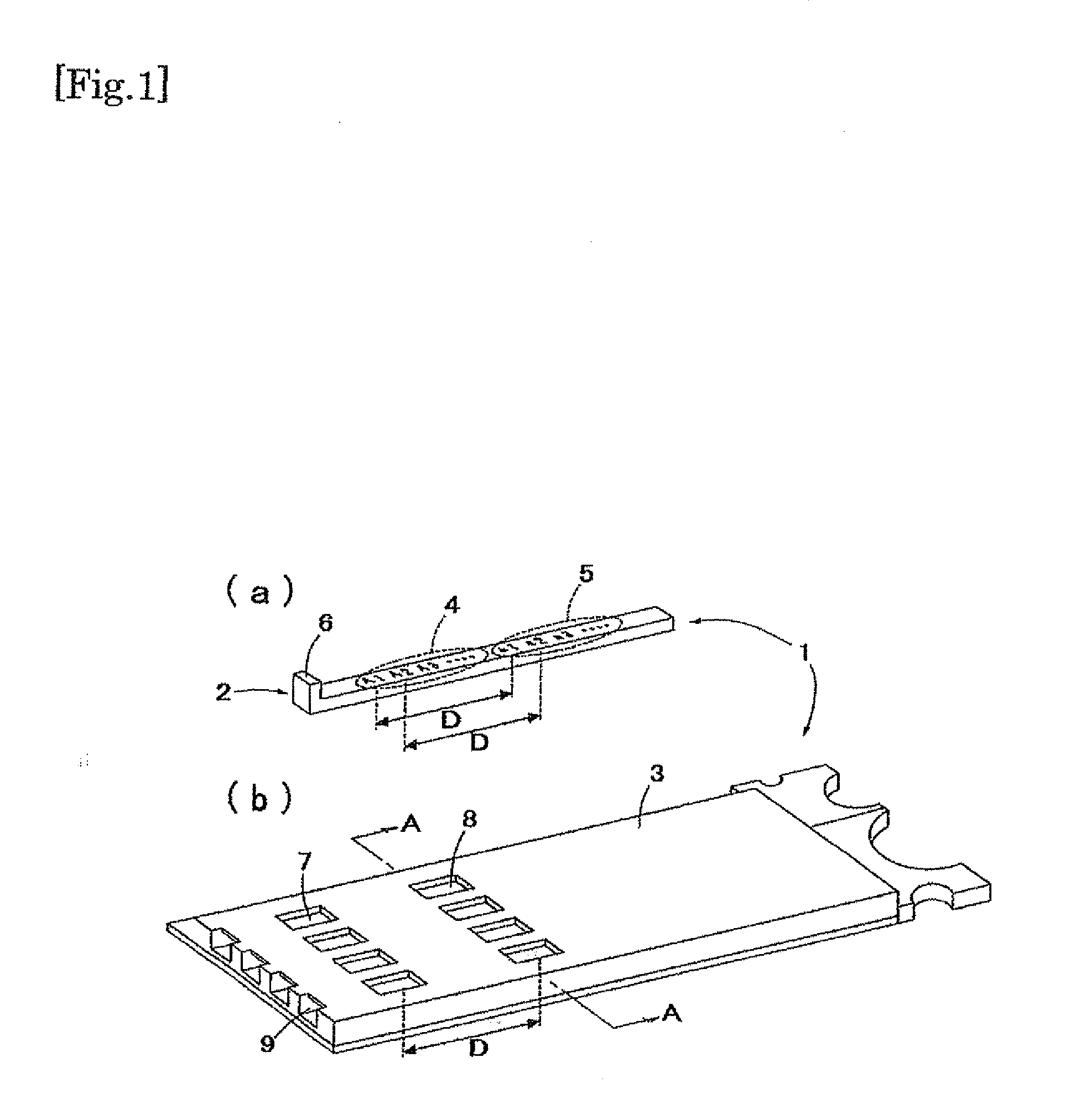
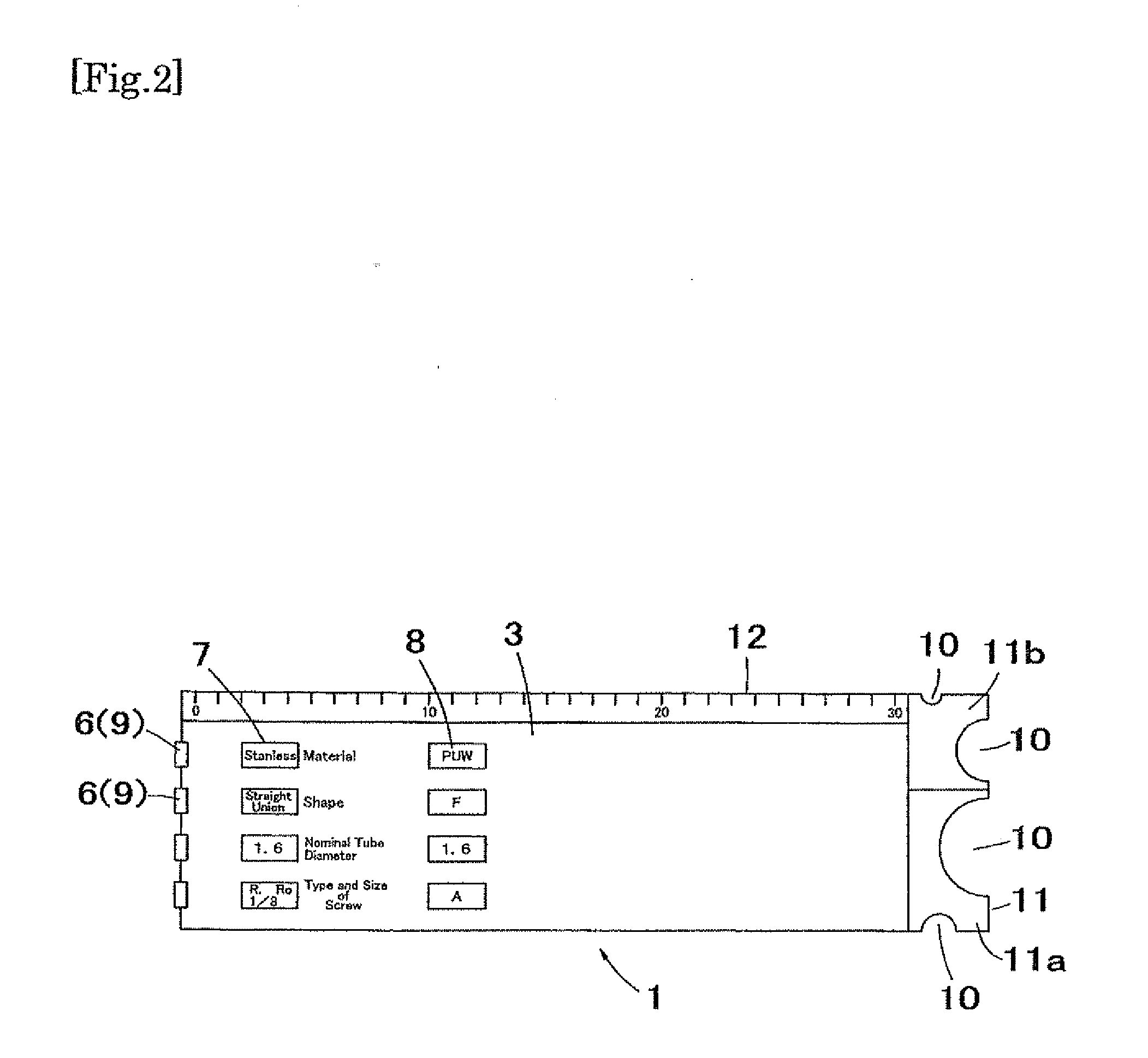
[0052]Further, the term “condition item” means a condition which is defined by those skilled in the art when setting the joint part number. For example, as shown in FIG. 2, there are 4 condition items such as “material”, “shape”, “nominal tube diameter” and “type and size of screw”. These items are properly set depending on an application or a type of the joint.

[0053]The term “condition(s)” used herein means the conditions from which a user determines selected conditions. The “condition item” is consisted of a plurality of “conditions”. For example, the “material”, which is one of the “condition ite...


PUM


Abstract

A jig for selecting a valve part number or a joint part number represented by a combination of selected symbols representing respective selected conditions required for selecting a valve or a joint comprising: a substantially rectangular base plate defining an inner space, and a plurality of linear sliding gauge laterally arranged in the inner space to slide in a longitudinal direction of the base plate, the sliding gauge comprising a condition description area including a plurality of conditions thereon from which the selected condition is determined, and a symbol description area including a plurality of symbols thereon, both the conditions and the symbols arranged in a sliding direction of the sliding gauge, a plurality of condition selecting windows laterally arranged on a top of the base plate, each condition selecting window configured to expose one of the selected conditions, a plurality of symbol selecting windows laterally arranged on the top of the base plate longitudinally apart from the condition selecting windows, respectively, each symbol selecting window configured to one of the selected symbols, wherein a distance between both windows is equivalent to a fixed distance between each of the symbols in the symbol description area and its corresponding condition in the condition description area.

Description

CROSS REFERENCE TO RELATED APPLICATIONS[0001]This application is International Application No. PCT / JP2008 / 057524, filed on Apr. 17, 2008, which claims priority of Japanese Patent Application No. 2007-173099, filed on Jun. 29, 2007, the entire content and disclosure of the preceding applications are incorporated by reference into this application.BACKGROUND OF THE INVENTION[0002]1. Field of the Invention[0003]This invention relates to a jig for selecting a valve part number or a joint part number which is able to accurately and quickly select a desired valve or a joint for usage of a valve or a joint.[0004]2. Description of the Related Art[0005]There are numerous kinds of valve or joint, for example, a valve for opening and closing a space (pipe) in which gas or water flows or a valve having a function of controlling the flow of gas or water, or a joint for connecting tubes. This wide variety of valve or joint enables a user to select the valve or joint most appropriately and effecti...

Claims


Application Information

Patent Timeline
Patent Type & Authority Applications(United States)
IPC IPC(8): G09F9/00
CPCG06C3/00G01B3/04G09F11/232G01M3/08
Inventor MIYAGAWA, HIDEYUKINAKAHAMA, TAKAYASUKURIYAMA, SYUICHI
Owner FUJIKIN INC
Why Eureka
Try Eureka