Method of prevention of hydrates

a technology of hydrates and hydrates, applied in the direction of insulation, mechanical equipment, borehole/well accessories, etc., can solve the problems of increasing the number of hydrates in the pipeline, and substantial additional cooling, so as to prevent the formation of hydrates

Inactive Publication Date: 2010-03-04
BAUGH PAULA B +1
View PDF7 Cites 30 Cited by
  • Summary
  • Abstract
  • Description
  • Claims
  • Application Information

AI Technical Summary

Benefits of technology

[0010]The object of this invention is to provide a method for the prevention of the formation of hydrates in subsea pipes when subsea valves are opened.
[0011]A second object of the present invention is to provide a method for the removal of hydrates and / or wax blockages which have formed in subsea pipes.

Problems solved by technology

There is a tendency for hydrates to form in pipelines departing from a subsea gas well, especially during well flow startup.
When a subsea valve is opened, the gas expansion can cause substantial additional cooling.
This means that not only can the expansion of this gas keep the formed hydrate cool, but can literally continue to grow additional hydrate blockage.
This is an expensive operation due to the cost of the equipment and the time delay in arranging for and deploying the equipment.
Removal by the use of coiled tubing is further complicated if there are bends in the pipeline, making it more difficult to impossible.
In addition to the chemicals being expensive, the delivery of the chemicals to the remote location of the likely hydrate formation requires expensive capital equipment.

Method used


Image

  • Method of prevention of hydrates
  • Method of prevention of hydrates
  • Method of prevention of hydrates

Examples


Embodiment Construction

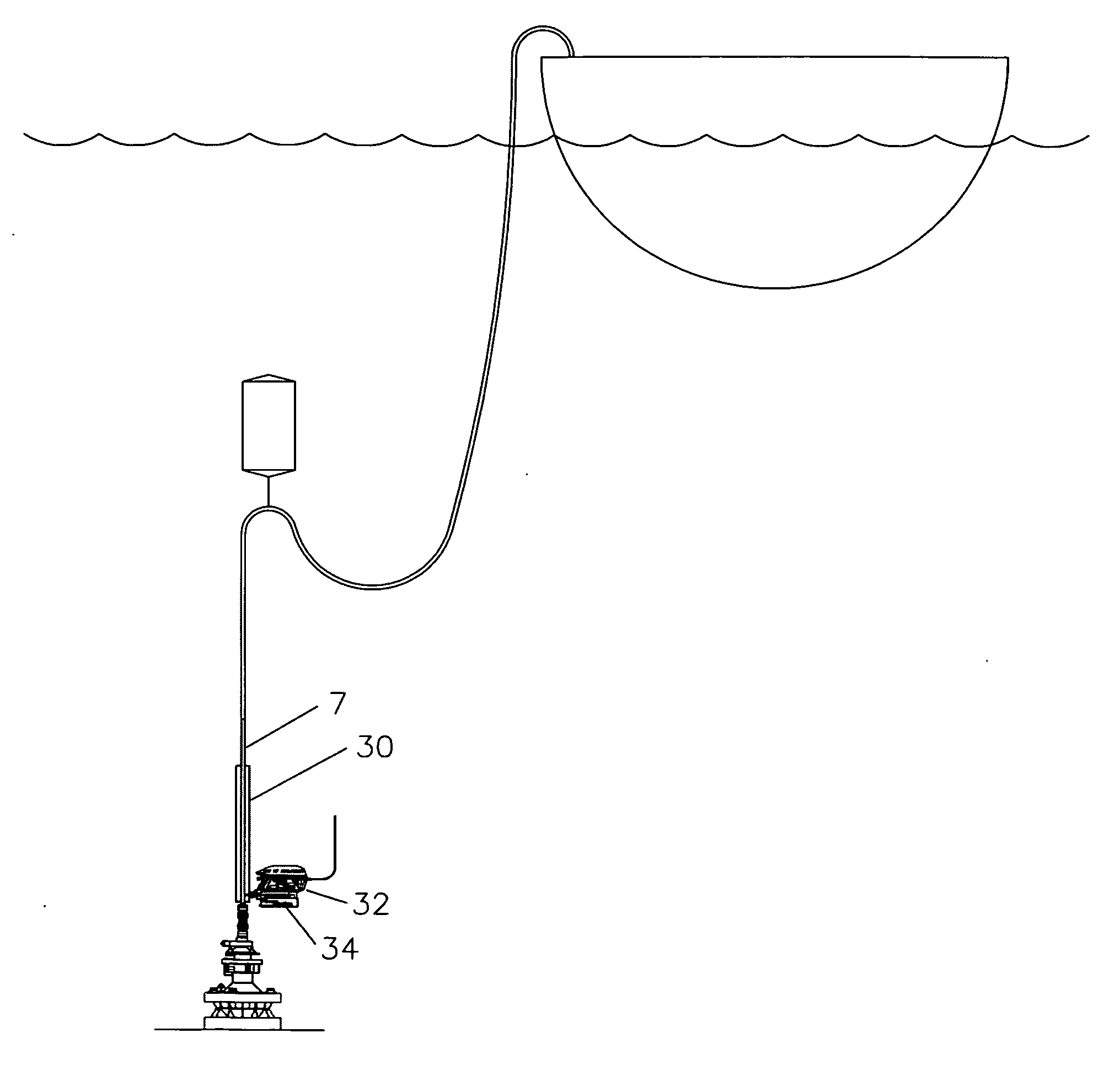
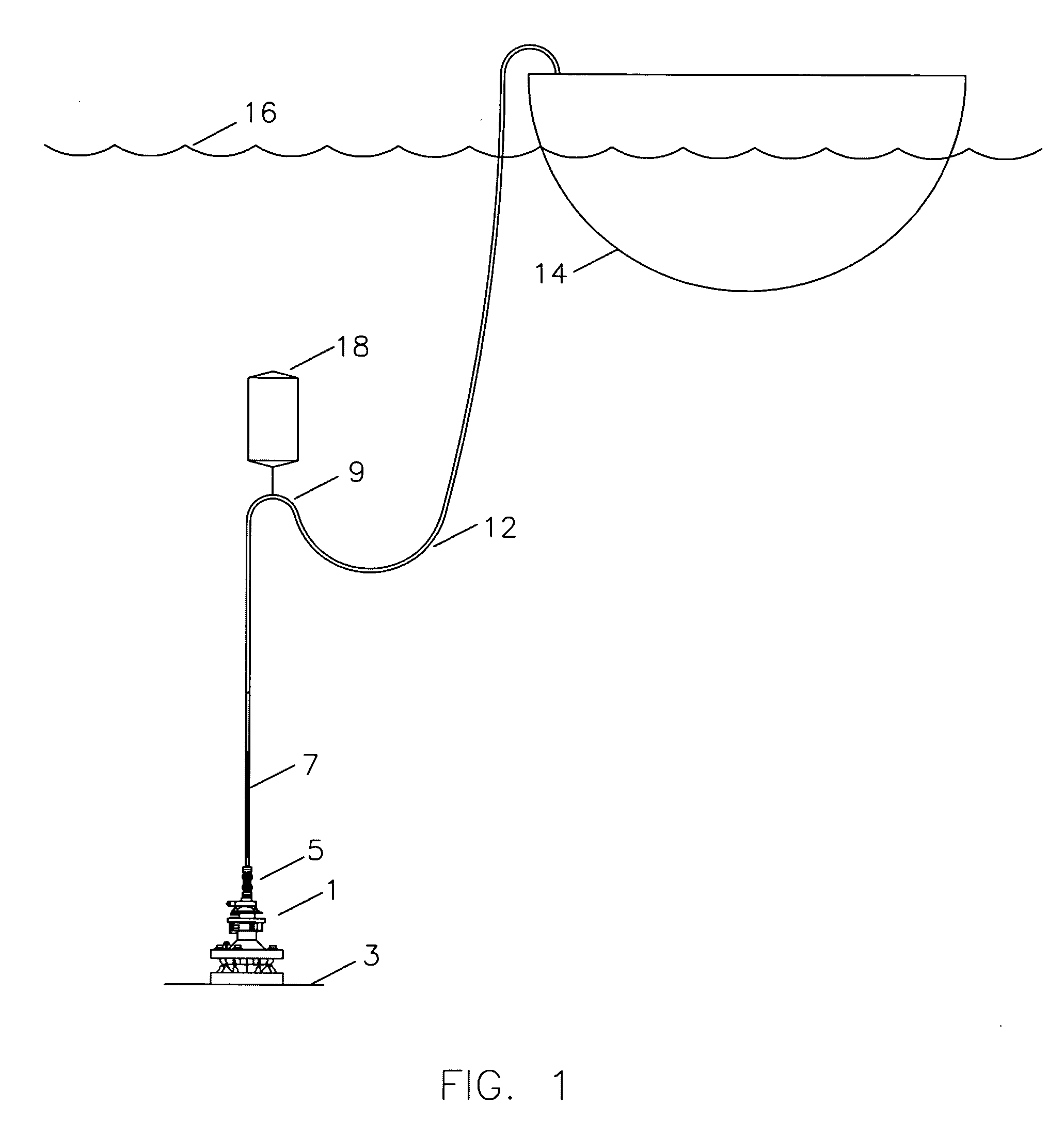
[0016]FIG. 1 shows a subsea installation 1, landed on the seafloor 3, a valve 5 to be opened, a riser pipe 7, a gooseneck 9, a flexible pipe 12, a surface vessel 14, at the ocean's surface 16, and a buoyant tank 18 to support the riser pipe 7.

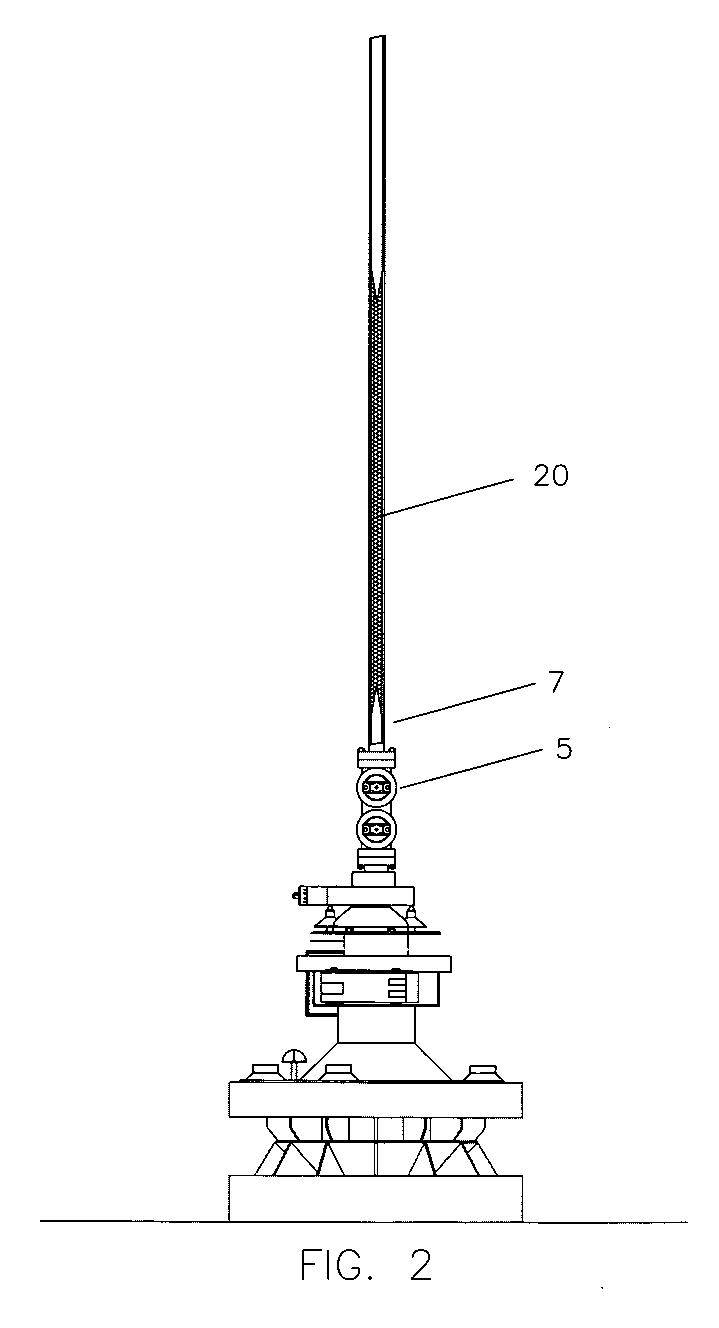
[0017]Referring now to FIG. 2, valve 5 has been closed for an extended period of time sufficient for all equipment and liquids to have been cooled to the temperature of the sea water, presumably 34° F. Valve 5 was opened and the cooled high pressure gas throttled across the opening valve into the lower pressure area in the riser pipe 7 above the valve. The blast of gas (probably methane) with a water content literally begins to freeze into a hydrate ice on the internal walls of the riser pipe 7 to the point of complete blockage as indicates as 20. At this time the operation has been required to wait until the hydrate melted of its own accord, in temperatures as low as 34° F.

[0018]Referring again to FIG. 1, access to the hydrate for mechanical r...


PUM


Abstract

The method of prevention of hydrate formation inside a subsea pipe of a first temperature during an increase in flow within the pipe comprising containing a volume of water outside the pipe, heating the volume of water to a second temperature higher than the first temperature such that the pipe is heated to a temperature high enough to stop the formation of the hydrates, and increasing the flow in the pipe.

Description

CROSS-REFERENCE TO RELATED APPLICATIONS[0001]N / ASTATEMENT REGARDING FEDERALLY SPONSORED RESEARCH OR DEVELOPMENT[0002]N / AINCORPORATION-BY-REFERENCE OF MATERIAL SUBMITTED ON A COMPACT DISK[0003]N / ABACKGROUND OF THE INVENTION[0004]The field of this invention is that of preventing hydrate blockages in subsea pipelines, subsea riser pipes, and subsea equipment installations.[0005]Hydrates are a porous solid which is formed primarily of water with a mixture of gases. It is effectively similar to crushed ice which is stuck together. There is a tendency for hydrates to form in pipelines departing from a subsea gas well, especially during well flow startup.[0006]The temperature of the seawater at depths will often approach 34° F., with the temperature in a non-blowing pipe being the same. When a subsea valve is opened, the gas expansion can cause substantial additional cooling. In these cold and high pressure conditions, hydrates of the gas and water quickly form.[0007]Frequently when the hy...

Claims


Application Information

Patent Timeline
Patent Type & Authority Applications(United States)
IPC IPC(8): E21B36/00
CPCE21B43/01E21B17/015
Inventor BAUGH, PAULA B.BAUGH, BENTON F.
Owner BAUGH PAULA B
Why Eureka
Try Eureka