
Intensity-Based One-Way Visible Display System

Inactive Publication Date: 2010-03-04
EMISCAPE
View PDF1 Cites 2 Cited by
  • Summary
  • Abstract
  • Description
  • Claims
  • Application Information

AI Technical Summary

Benefits of technology

[0008]A portion of the intermediate light passes through the partially absorptive screen and exits as transmitted light to the dark side of the display. The inverse image on the partially absorptive screen absorbs (or otherwise redirects) another portion of the intermediate light so that the transmitted light is spatially and chromatically uniform like the ambient light. By countering the effects of the image on the partially reflective screen, the inverse image on the partially absorptive screen allows the observers on the dark side to see objects on the bright side without the image on the partially reflective screen.

Problems solved by technology

However, advertisements on the side of a building cover up what otherwise would be space for windows in the building.

Method used


Image

  • Intensity-Based One-Way Visible Display System
  • Intensity-Based One-Way Visible Display System
  • Intensity-Based One-Way Visible Display System

Examples


Embodiment Construction

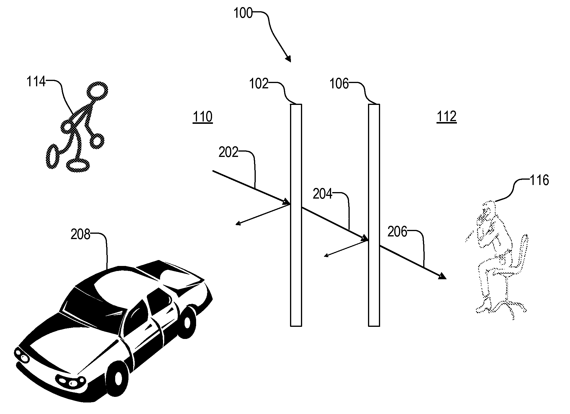
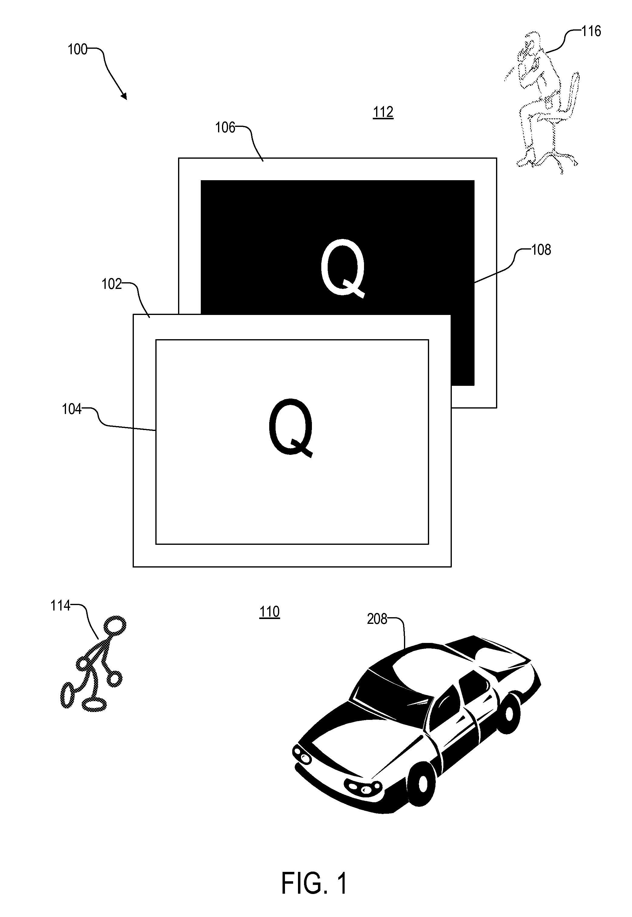
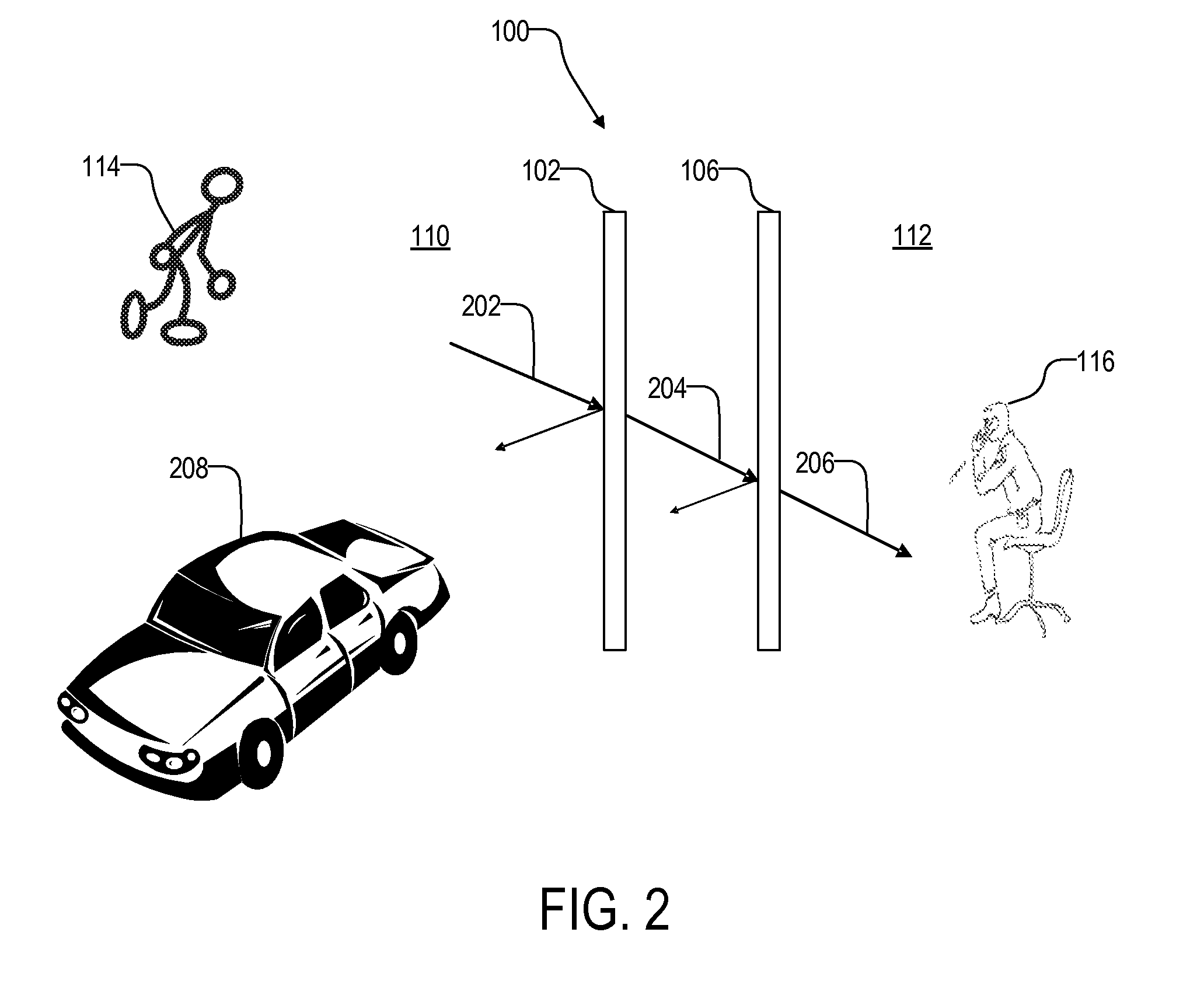
[0012]FIG. 1 illustrates an intensity-based one-way visible display system 100 in one embodiment of the invention. Display system 100 includes a partially reflective screen 102 with an image 104, and a partially absorptive screen 106 with an inverse image 108 of image 104. Screens 102 and 106 are adjacent and substantially parallel to each other. Screens 102 and 106 are illustrated as being separated by a large distance to demonstrate the concepts of the present invention but in practice they may be separated by a small gap or stacked on top of each other.

[0013]Display system 100 separates two environments where partially reflective screen 102 faces a relatively bright side 110 and partially absorptive screen 106 faces a relatively dark side 112. Typically display system 100 is, or forms part of, a window of a building so the exterior of the building is bright side 110 and the interior of the building is dark side 112.

[0014]Partially reflective screen 102 presents image 104 to obser...


PUM


Abstract

A one-way display system includes a partially reflective screen with a first image, and a partially absorptive screen with a second image that is an inverse of the first image. The two screens can be stacked on top of each other or separated by a small distance. A portion of ambient light on a first side of the display system passes through the partially reflective screen and exits as intermediate light. A portion of the intermediate light passes through the partially absorptive screen and exits as transmitted light to a second side of the display system. The transmitted light is spatially and chromatically uniform like the ambient light. This allows observers on the second side to see objects on the first side without the first image, and observers on the first side to see the first image.

Description

CROSS REFERENCE TO RELATED APPLICATION[0001]This application is related to (1) U.S. patent application Ser. No. 11 / 109,543, now U.S. Pat. No. 7,213,930, entitled “Polarized Projection Display,” filed on Apr. 18, 2005, (2) U.S. patent application Ser. No. 11 / 686,195, entitled “Polarized Projection Display,” filed on Mar. 14, 2007, (3) U.S. patent application Ser. No. 11 / 367,687, entitled “One-Way Transparent Display Systems,” filed on Mar. 3, 2006, and (4) U.S. patent application Ser. No. 11 / 626,247, entitled “Projection Display with Holographic Screen,” filed on Jan. 23, 2007, (5) U.S. patent application Ser. No. 11 / 782,597, entitled “One-Way Display Using Color Filter,” filed on Jul. 24, 2007, which are incorporated herein by reference, and (6) U.S. patent application Ser. No. 11 / 951,183, entitled “Reflective One-Way Screen with Chromatic and Transparent Regions,” filed on Dec. 5, 2007.FIELD OF INVENTION[0002]This invention relates to displays, and specifically to transparent displ...

Claims


Application Information

Patent Timeline
IPC IPC(8): G02B27/10
CPCG09F19/14G09F13/12
Inventor QUACH, CANG V.ALVAREZ, DONALD L.
Owner EMISCAPE
Features
  • Generate Ideas
  • Intellectual Property
  • Life Sciences
  • Materials
  • Tech Scout
  • Unparalleled Data Quality
  • Higher Quality Content
  • 60% Fewer Hallucinations
Learn More