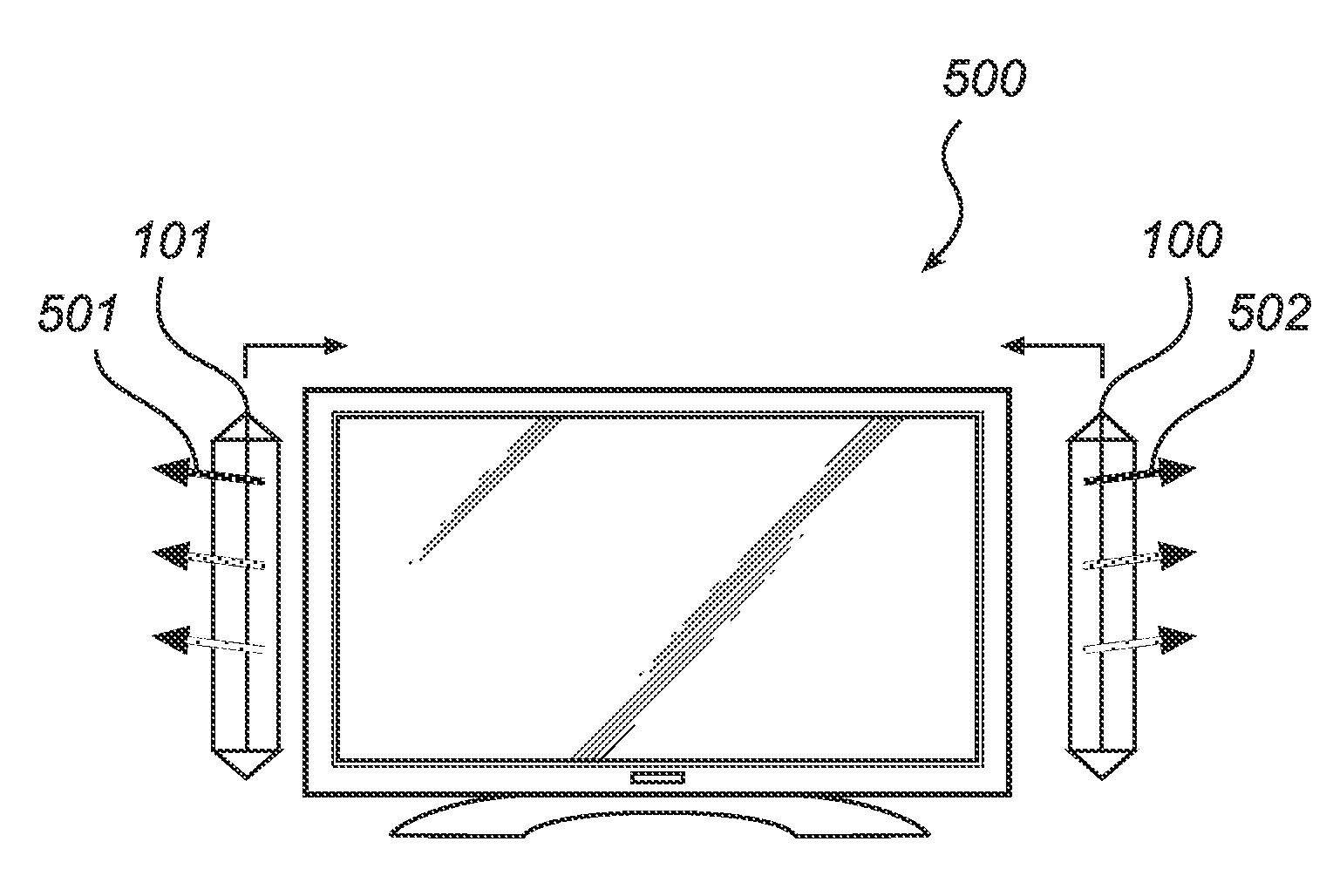
Symmetrical light guide structure for LED based ambilight
a technology of led ambilight and light guide structure, which is applied in the direction of lighting and heating apparatus, instruments, mechanical equipment, etc., can solve the problems of significant increase in the cost of a solution, serious drawbacks of solution, and colour mixing and colour uniformity associated with led use, and achieves the effect of slimming, small size and slimming
- Summary
- Abstract
- Description
- Claims
- Application Information
AI Technical Summary
Benefits of technology
Problems solved by technology
Method used
Image

Examples
Embodiment Construction
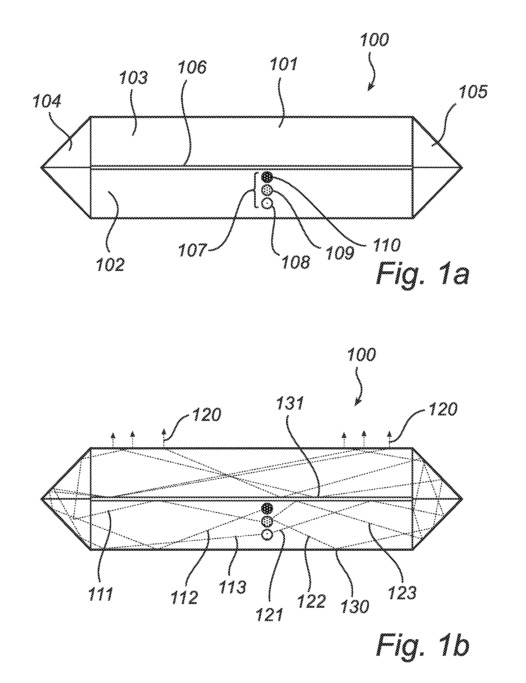
[0035]FIG. 1 shows a device 100 comprising a light guide 101, light input means 102, light output means 103, optical prisms 104 and 105, a void 106 and a set 107 of light emitting elements 108, 109 and 110. The void 106 is delimited by the double horizontal line in the middle of the device, and in a preferred embodiment according to the invention, the void constitutes an air gap. Alternatively to air, the space or void between the light input and light output sections may comprise vacuum or a fluid. The light emitting elements are situated in the light input means 102. Section a) of FIG. 1 illustrates the components of the device 100, and section b) illustrates a ray tracing simulation on the device 100 where arrows 111, 112, 113, 121, 122, and 123 indicate paths of travel from the light emitting elements 108, 109 and 110 until emerging 120 from the light output means 102 of the light guide 101. Also indicated are reflections 130 and 131 against the walls of the light guide 101. The...
PUM
 Abstract
Description
Claims
Application Information
 - R&D
- Intellectual Property
- Life Sciences
- Materials
- Tech Scout
- Unparalleled Data Quality
- Higher Quality Content
- 60% Fewer Hallucinations
Browse by: Latest US Patents, China's latest patents, Technical Efficacy Thesaurus, Application Domain, Technology Topic, Popular Technical Reports.
© 2025 PatSnap. All rights reserved.Legal|Privacy policy|Modern Slavery Act Transparency Statement|Sitemap|About US| Contact US: help@patsnap.com