Apparatus for generating pumping voltage

a technology of apparatus and pumping voltage, applied in the field of apparatus for generating pumping voltage, can solve the problems of failure and inability to accurately record data in cells, and achieve the effect of boosting pumping voltag

Inactive Publication Date: 2010-03-11
SK HYNIX INC
View PDF4 Cites 1 Cited by
  • Summary
  • Abstract
  • Description
  • Claims
  • Application Information

AI Technical Summary

Benefits of technology

[0017]An apparatus for generating pumping voltage capable of boosting pumping voltage at a high speed in a multi CS mode semiconductor memory apparatus is described herein.

Problems solved by technology

Accordingly, there are problems in that precise data is not recorded in cells and failure occurs.

Method used


Image

  • Apparatus for generating pumping voltage
  • Apparatus for generating pumping voltage
  • Apparatus for generating pumping voltage

Examples


Embodiment Construction

[0033]In the following description, a pumping voltage generation apparatus is provided with respect to each bank (bank0˜bank3), as an example, a 2CS mode in which CS0 signal controls operation of bank0 and bank1 of a first cell and CS1 signal controls operation of bank2 and bank3 of a second cell will be described.

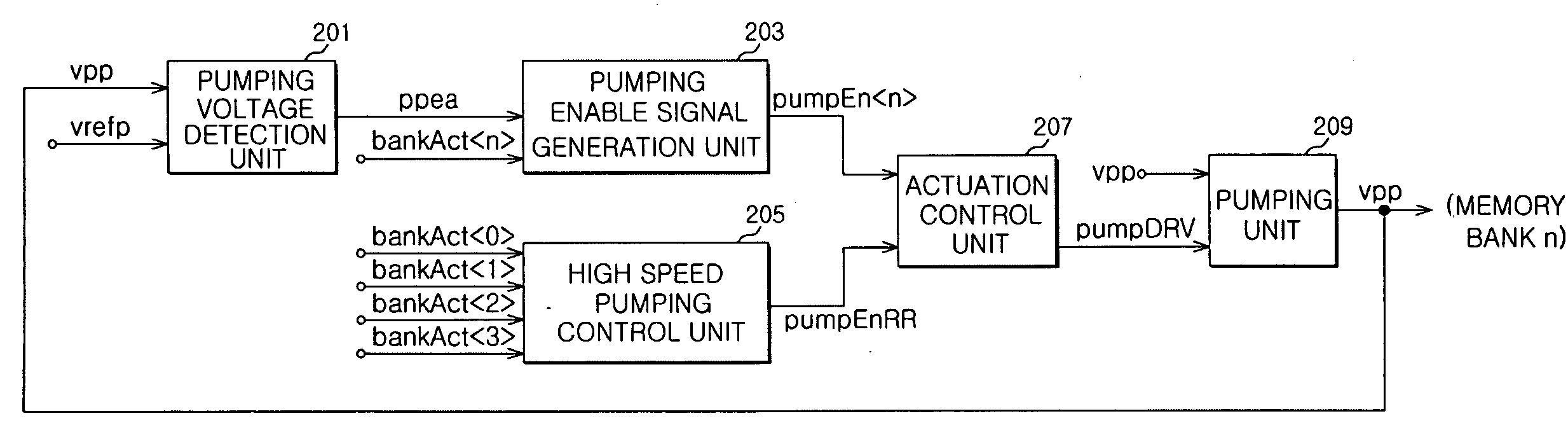
[0034]FIG. 4 is a schematic diagram of an exemplary apparatus for generating pumping voltage according to one embodiment. In FIG. 4, an apparatus for generating pumping voltage can include a pumping voltage detection unit 201, a pumping enable signal generation unit 203, a high speed pumping control unit 205, an actuation control unit 207, and a pumping unit 209.

[0035]The pumping voltage detection unit 201 can receive the pumping voltage vpp and a reference voltage vrefp to enable and output a pumping control signal ‘ppea’ when the pumping voltage is lower than the reference voltage. The pumping enable signal generation unit 203 can receive the pumping control signal ‘ppea...


PUM


Abstract

An apparatus for generating pumping voltage of a multiple Chip Select (CS) mode semiconductor memory apparatus includes a high speed pumping control unit configured to produce a pumping enable signal regardless of the level of a pumping voltage to actuate the pumping unit when a plurality of banks of the semiconductor apparatus operated by different CS signals are continuously actuated.

Description

CROSS-REFERENCES TO RELATED APPLICATION[0001]The present application claims priority under 35 U.S.C. §119(a) to Korean application number 10-2008-0088663, filed on Sep. 9, 2008, in the Korean Intellectual Property Office, which is incorporated herein by reference in its entirety as if set forth in full.BACKGROUND[0002]1. Technical Field[0003]The embodiments disclosed herein relate to an apparatus for generating pumping voltage, and more particularly, to an apparatus for generating pumping voltage capable of high speed bank actuation for a semiconductor memory apparatus operating in a multi-CS (Chip Select) mode.[0004]2. Related Art[0005]Generally, in a semiconductor memory apparatus, pins are commonly required to operate DRAM devices, wherein a Chip Select (CS) pin determines whether a specific DRAM is operated or not. For example, when the CS pin is enabled at a low level, the DRAM devices are functional, and when the CS pin is at a high level, the DRAM device are not functional re...

Claims


Application Information

Patent Timeline
Patent Type & Authority Applications(United States)
IPC IPC(8): G11C5/14
CPCG11C5/145G11C11/4074
Inventor CHOI, YOUNG KYOUNG
Owner SK HYNIX INC
Why Eureka
Try Eureka