

Image acquisition apparatus and biometric information acquisition apparatus
a biometric information and acquisition apparatus technology, applied in the field of image acquisition apparatus and biometric information acquisition apparatus, can solve the problems of difficult to effectively suppress crosstalk and easy forgery of authentication information, and achieve the effect of effectively suppressing crosstalk
- Summary
- Abstract
- Description
- Claims
- Application Information
AI Technical Summary
Benefits of technology
Problems solved by technology
Method used
Image

Examples
first embodiment
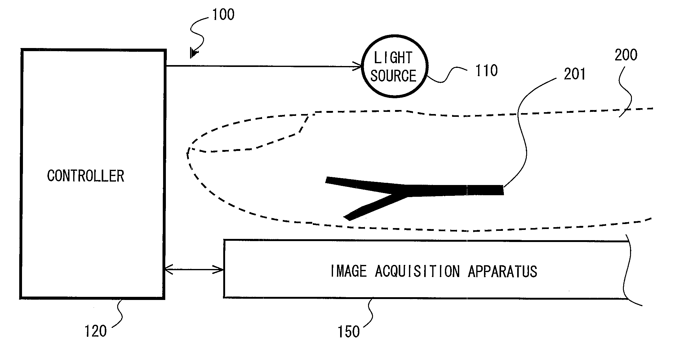
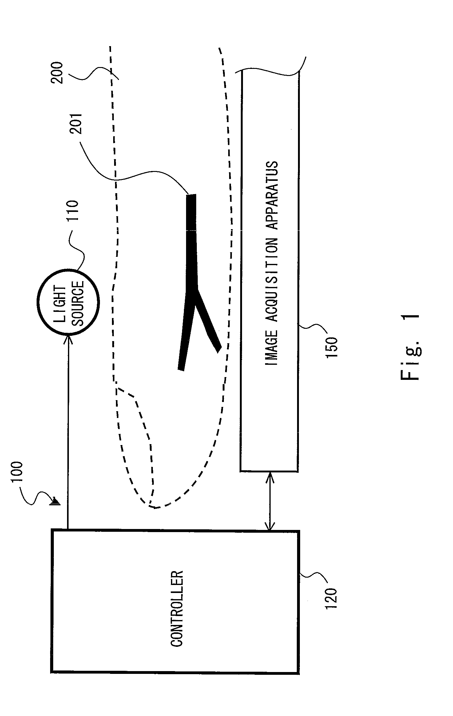
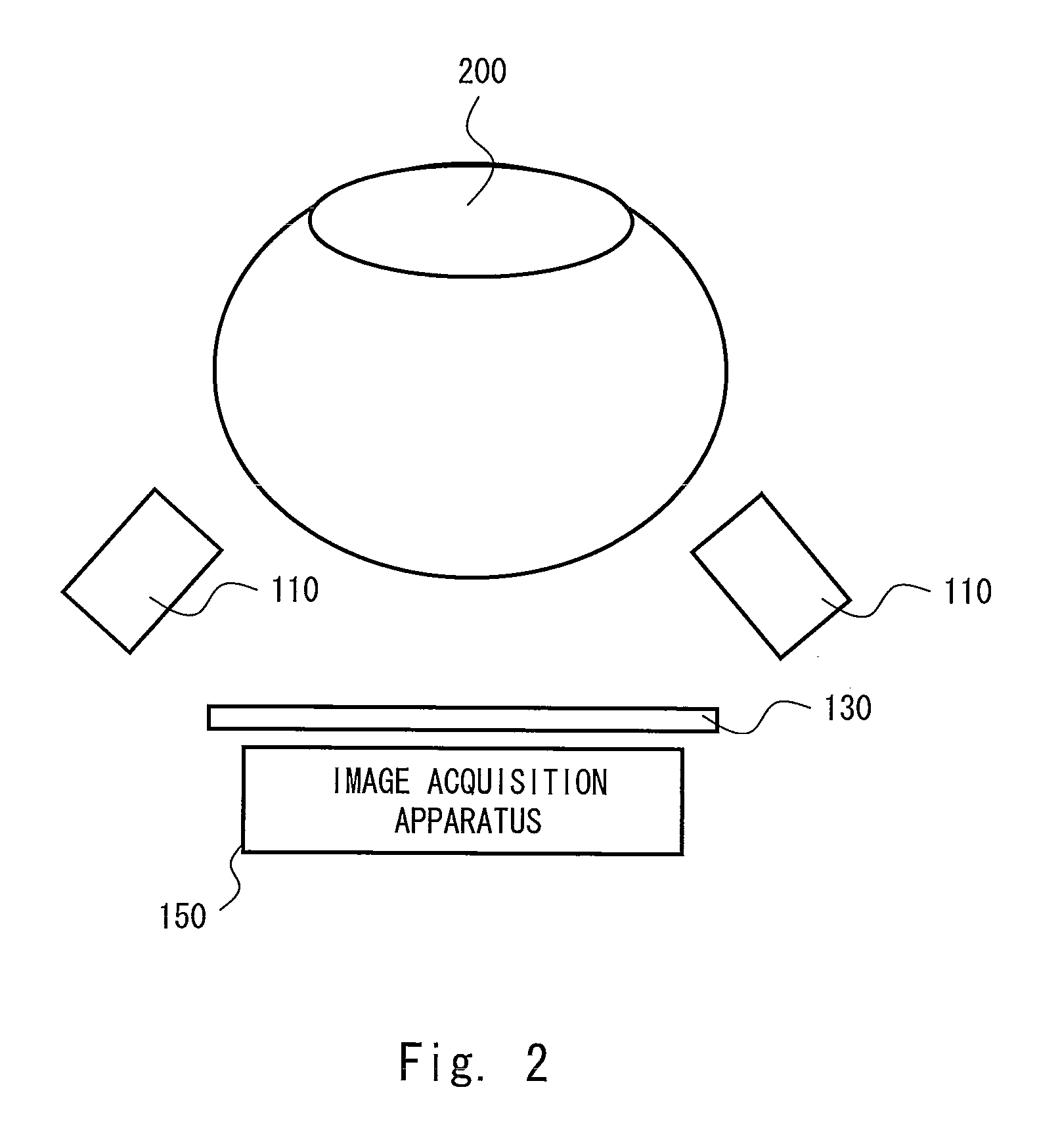
[0048]A first embodiment of the present invention is described hereinafter with reference to FIGS. 1 to 12. FIGS. 1 and 2 are explanatory views showing a schematic structure of a biometric authentication apparatus. FIG. 3 is a schematic cross-sectional view of an image acquisition apparatus. FIG. 4 is a graph to describe an effect of a filter layer. FIG. 5 is an explanatory view to describe an incident angle. FIG. 6 is an explanatory view to describe a positional relationship between a lens, an opening and a pixel. FIGS. 7A to 8E are process charts showing a method of manufacturing an image acquisition apparatus. FIG. 9 is an explanatory view showing a structure of a cellular phone incorporating a biometric authentication apparatus. FIG. 10 is a top view of a cellular phone in a folded state. FIG. 11 is a schematic block diagram showing a system configuration of a biometric authentication apparatus. FIG. 12 is a flowchart to describe an operation of a biometric authentication appara...
second embodiment
[0114]A second embodiment of the present invention is described hereinafter with reference to FIG. 13. FIG. 13 is a schematic cross-sectional view of an image acquisition apparatus.
[0115]In this embodiment, the optical function layer 20 has a structure in which the filter layer 21 and the light shielding layer 22 are placed on the principal surface of a transparent substrate (support substrate) 23. In such a case also, the same advantage as in the first embodiment can be obtained.
[0116]The transparent substrate 23 is a plate-shaped member and is substantially transparent to the output light of the light source 110. The transparent substrate 23 is a glass plate, for example.
[0117]In order to suppress the crosstalk, it is preferable to keep a sufficient optical distance between the light shielding layer 13 and the light shielding layer 22. In the case of forming a thick resin layer between the light shielding layer 13 and the light shielding layer 22 by a normal coating technique, the...
third embodiment
[0120]A third embodiment of the present invention is described hereinafter with reference to FIG. 14 and FIGS. 15A to 15D. FIG. 14 is a schematic cross-sectional view of the image acquisition apparatus 150. FIGS. 15A to 15D are schematic manufacturing process charts of the optical function layer 20.
[0121]In this embodiment, the filter layer 21 is placed on the lower surface of the transparent substrate 23. In such a case also, the same advantage as in the first and second embodiments can be obtained. Specifically, by the filtering effect of the filter layer 21, incident light with a small incident angle passes through the filter layer 21, and incident light with a large incident angle is blocked by the filter layer 21. It is thereby possible to reduce the crosstalk and acquire a higher quality vein image.
[0122]As shown in FIG. 14, an opening OP2a, an opening OP1a and a lens 32a are arranged coaxially above a pixel 14a. Above a pixel 14b, an opening OP2b, an opening OP1b and a lens 3...
PUM
 Abstract
Description
Claims
Application Information