
Light-emitting ball

a technology of light-emitting balls and sports balls, applied in the field of balls, can solve the problems of dull appearance of sports balls, and achieve the effect of effective promotion of visual effects

Inactive Publication Date: 2010-03-18
LIN KENG HSIEN
View PDF10 Cites 101 Cited by
  • Summary
  • Abstract
  • Description
  • Claims
  • Application Information

AI Technical Summary

Benefits of technology

[0007]Therefore, the object of the present invention is to provide a light-emitting ball, which can effectively promote visual effects.

Problems solved by technology

However, even if the patterns or the colors can be changed, an appearance of the sports ball 1 remains dull.

Method used


Image

  • Light-emitting ball
  • Light-emitting ball
  • Light-emitting ball

Examples


Embodiment Construction

[0018]Before the present invention is described in greater detail, it should be noted that like components are assigned the same reference numerals throughout the following disclosure.

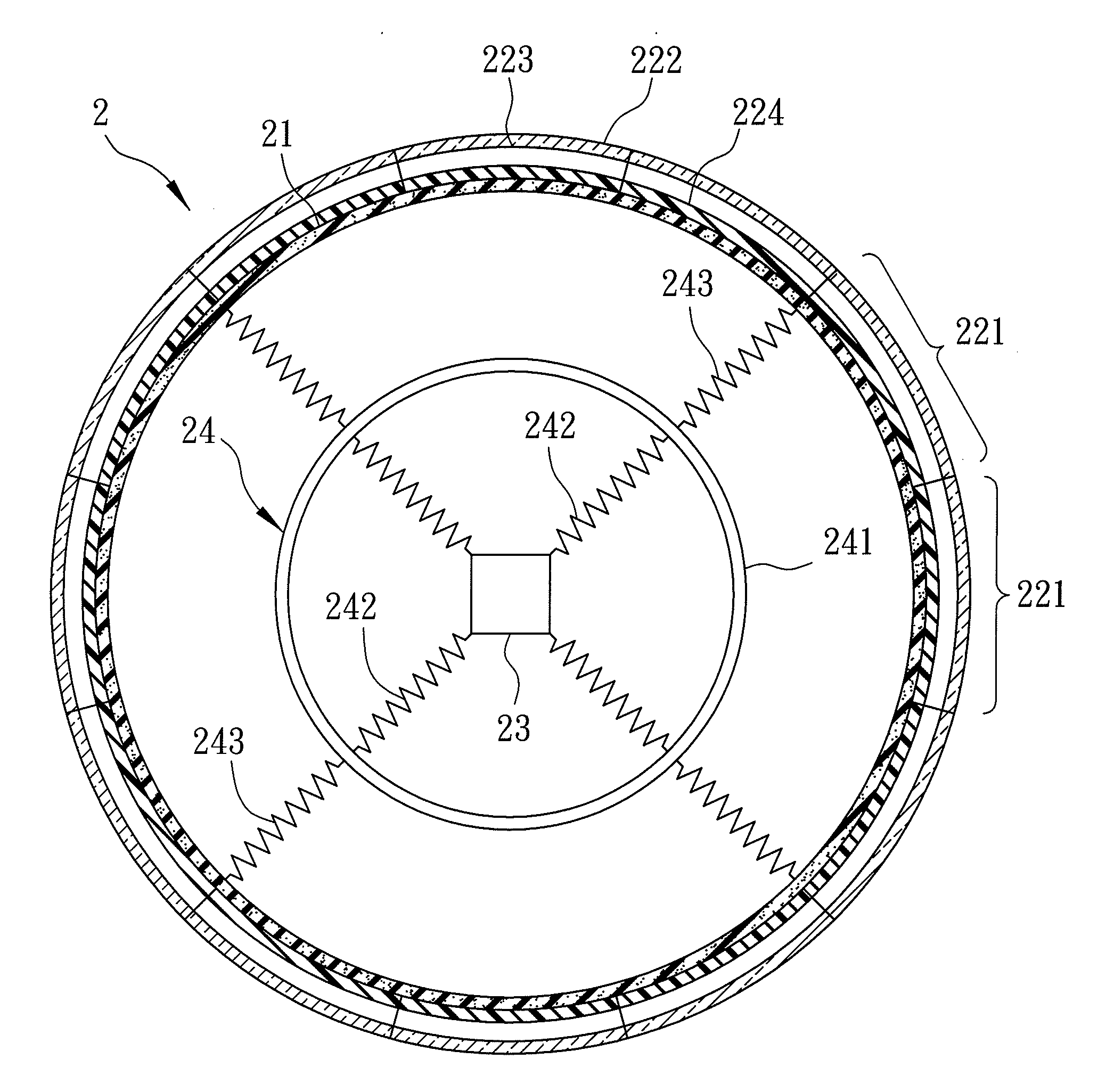
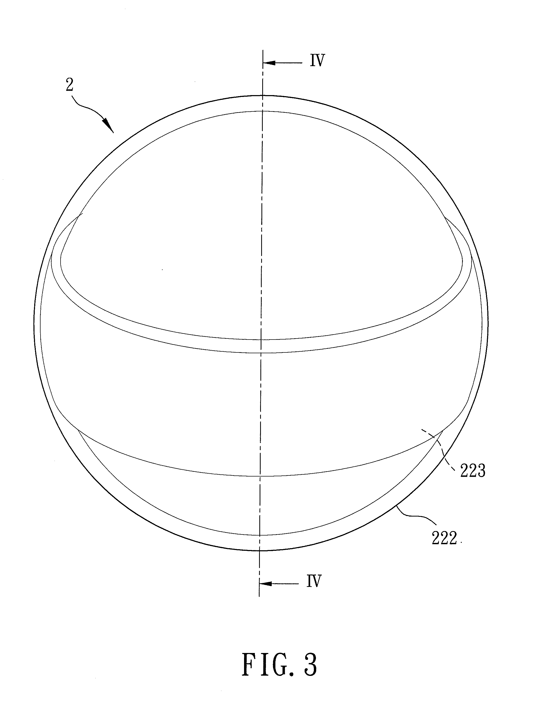
[0019]Referring to FIGS. 3 and 4, a first preferred embodiment of a light-emitting ball 2 according to the present invention is shown to comprise an inflatable ball bladder 21, a transparent skin layer 222, and an electrically operable display module 223.

[0020]The transparent skin layer 222 encloses the ball bladder 21. The electrically operable display module 223 is disposed between the ball bladder 21 and the skin layer 222, is attached to an inner surface of the skin layer 222, and is operable to generate images visible through the skin layer 222. The display module 223 has a shape of an annular band in this embodiment, and includes a remotely controllable battery-operated power supply unit 227 for supplying electric power thereto.

[0021]In this embodiment, the skin layer 222 is made of a thermoplast...


PUM


Abstract

A light-emitting ball includes an inflatable ball bladder, a transparent skin layer that encloses the ball bladder, and an electrically operable display module, such as a flexible organic light emitting diode (OLED) display module, that is disposed between the ball bladder and the skin layer and that is operable to generate images visible through the skin layer.

Description

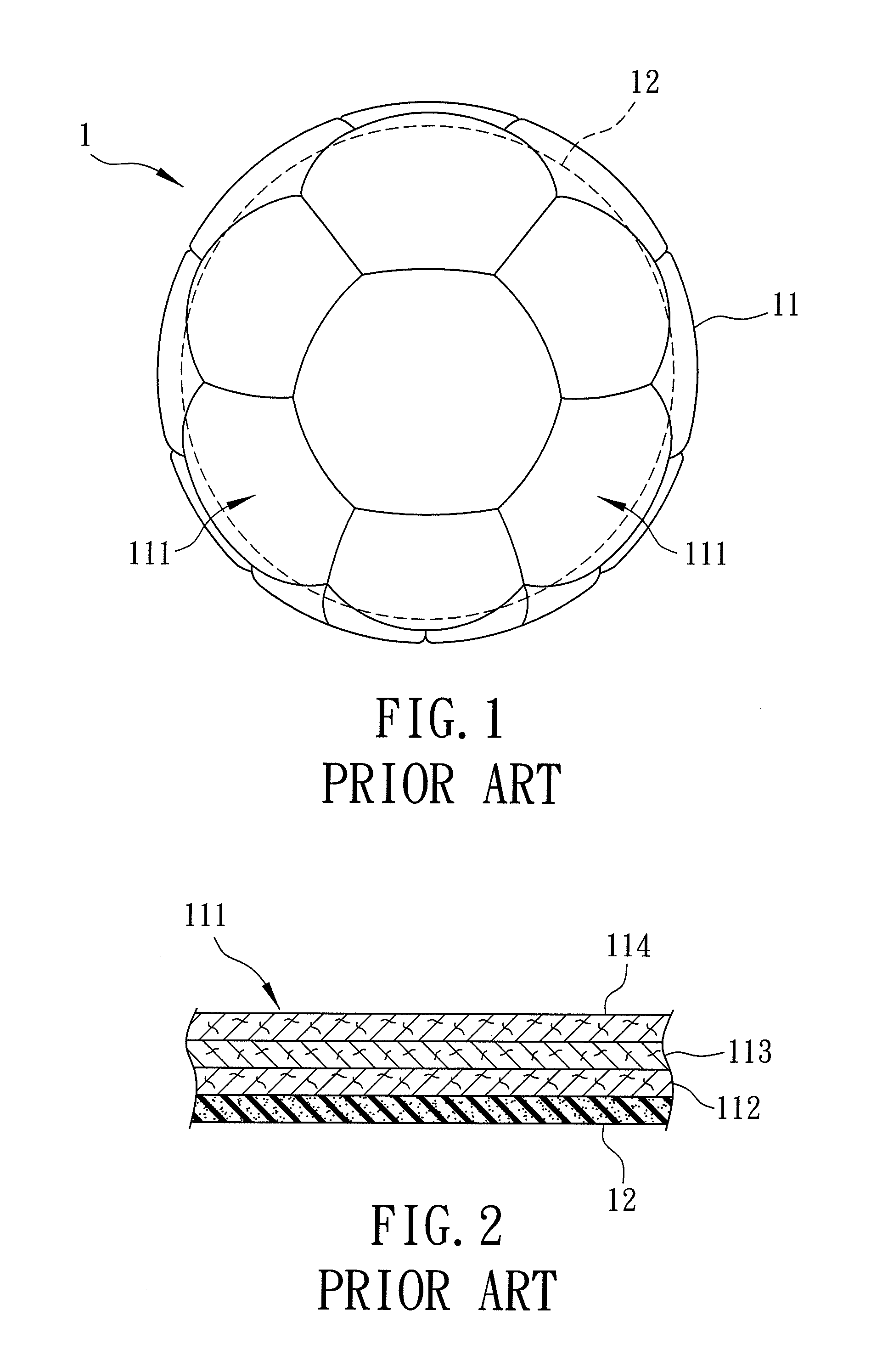
CROSS-REFERENCE TO RELATED APPLICATION[0001]This application claims priority of Taiwanese Application No. 097135320, filed on Sep. 15, 2008.BACKGROUND OF THE INVENTION[0002]1. Field of the Invention[0003]The present invention relates to a ball, more particularly to a light-emitting ball.[0004]2. Description of the Related Art[0005]Sport activities played with a ball are popular. Examples of such sport activities include baseball, basketball, soccer, volleyball, softball, and so on.[0006]Referring to FIGS. 1 and 2, a conventional sports ball 1 includes an inflatable ball bladder 12 and a skin layer 11 that encloses the ball bladder 12. The skin layer 11 has a plurality of interconnected patch segments 111 enclosing the ball bladder 12. Each of the patch segments 111 has a backing layer 112 attached to an outer surface of the ball bladder 12, an intermediate layer 113 disposed on an outer surface of the backing layer 112, and an outer layer 114 disposed on an outer surface of the inte...

Claims


Application Information

Patent Timeline
IPC IPC(8): A63B43/06A63B41/00
CPCA63B43/06A63B71/0622A63B2071/0683A63B2225/50A63B2220/12A63B2220/40A63B2207/02A63B2225/74
Inventor LIN, KENG-HSIEN
Owner LIN KENG HSIEN
Learn More