
Wig and method of making the same

Inactive Publication Date: 2010-03-25
UNIHAIR COMPANY LIMITED
View PDF21 Cites 15 Cited by
  • Summary
  • Abstract
  • Description
  • Claims
  • Application Information

AI Technical Summary

Benefits of technology

[0013]According to the wig of the present invention, the wig wearer can easily open a part of a wig base from a forehead portion, roll up backward a part of the wig base including a front portion of the wig base, and take care of or wash scalp covered with the wig base and own hair growing on the scalp. Moreover, the wearing state can be returned to the similar state before caring by the wig wearer him- or herself.
[0014]According to the method of making a wig of the present invention, the wig can be made which is capable of opening a part of a wig base from a forehead portion, washing or taking other care, and forming a hair style similar to that before caring.

Problems solved by technology

Therefore, the wig wearer can not always keep clean the own forehead, and can not help but rely on a specialist such as hair dressing technicians.

Method used


Image

  • Wig and method of making the same
  • Wig and method of making the same
  • Wig and method of making the same

Examples


Embodiment Construction

[0058]Hereinafter, explanation is made of the best modes for carrying out the present invention, referring to the drawings.

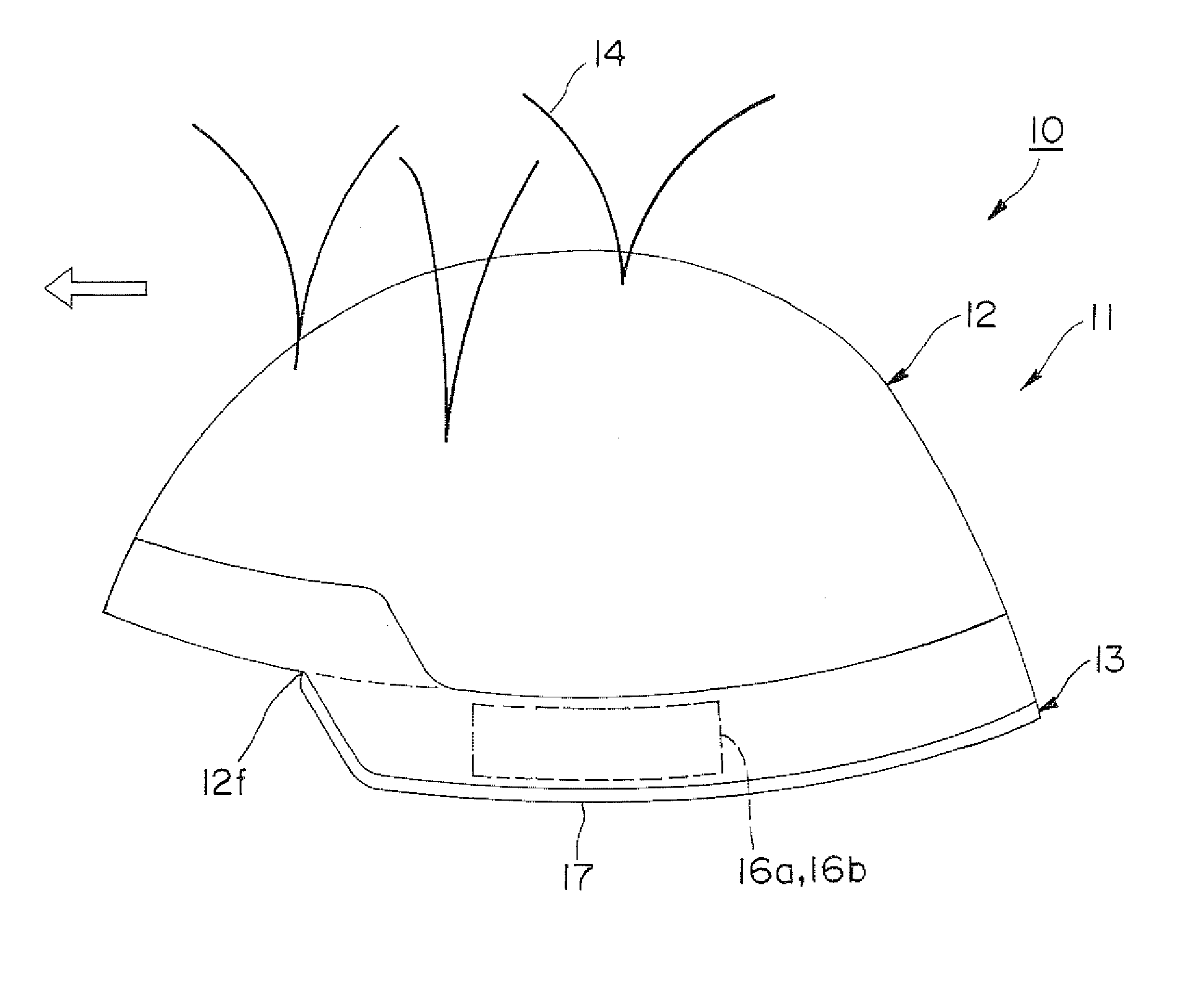
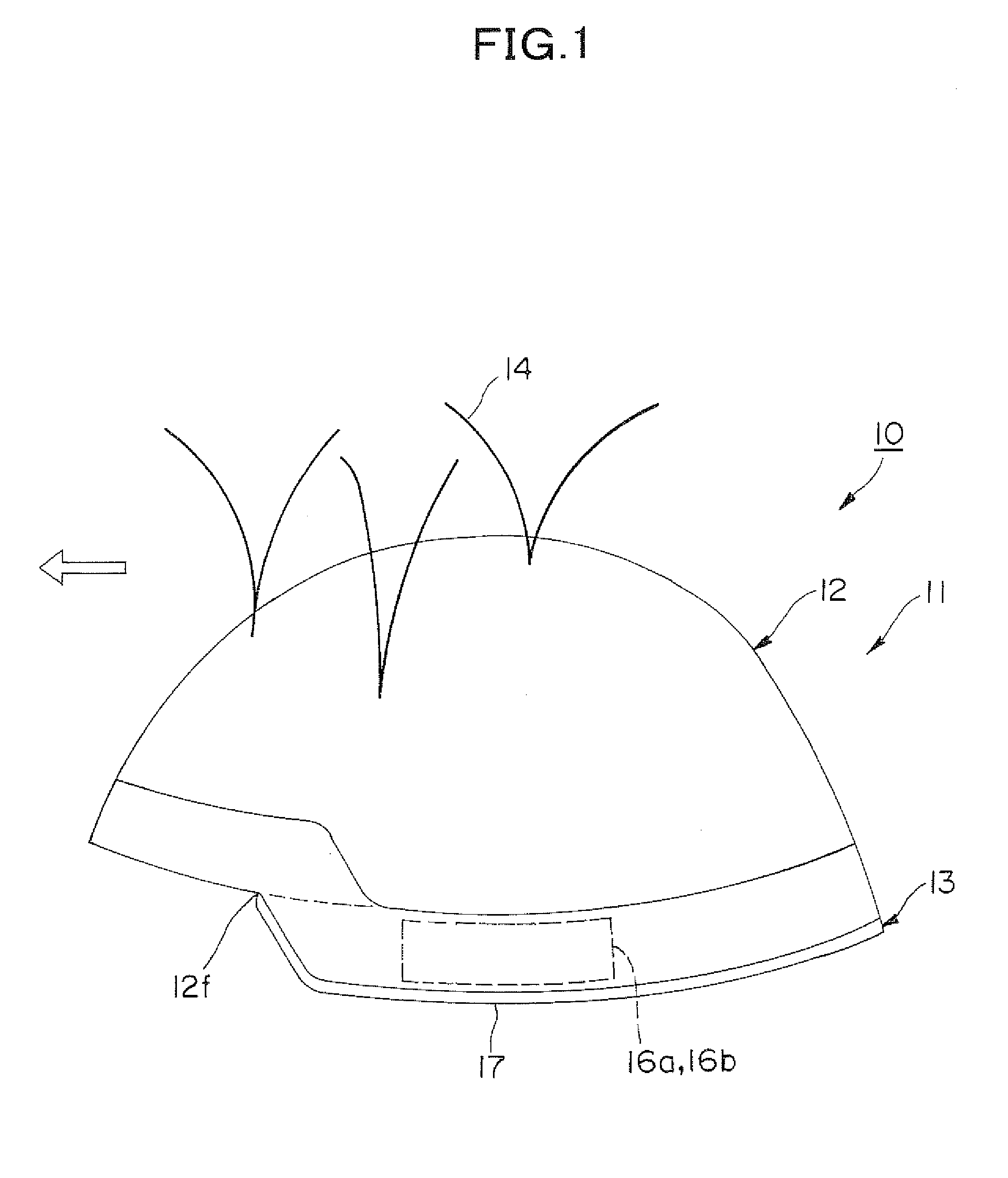
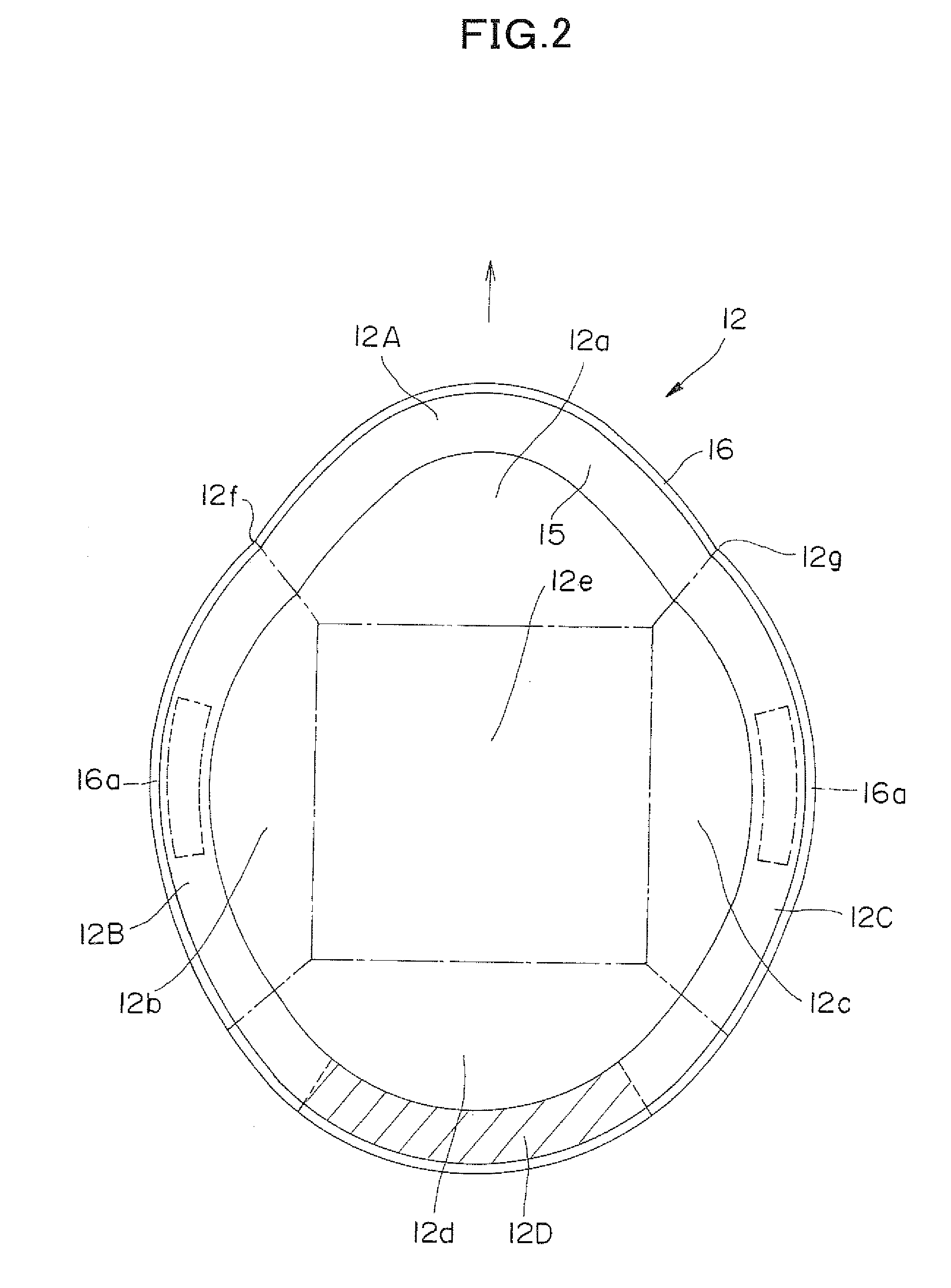
[0059]FIG. 1 is a left side view schematically showing a wig 10 in accordance with the embodiment. FIG. 2 is a plan view schematically showing a first base 12 constituting a part of the wig base 11 shown in FIG. 1. FIG. 3 is a plan view schematically showing a second base 13 constituting a part of the wig base 11 shown in FIG. 1. The arrow marks in the figures indicate the wig wearer's forehead direction. The wig 10 of the present invention is constituted by attaching numerous strands of hair 14 to the wig base 11. Only a part of hair 14 is shown in FIG. 1.

[0060]The wig base 11 includes a first base 12 shown in FIG. 2 and a second base 13 shown in FIG. 3, thus formed for a partial wig. The first base 12 has a front portion 12a, a left side portion 12b, a right side portion 12c, a back portion 12d, and a top portion 12e, as shown in FIG. 2, so as to cover a wig w...


PUM


Abstract

A wig base (11) has a first base (12) and a second base (13), wherein the first base (12) has a front portion (12a), a left side portion (12b), a right side portion (12c), a back portion (12d), and a top portion (12e), and is formed in the convex shape resembling the wig wearer's head shape so as to cover a wig wearing region, wherein the second base (13) is extending belt-like in the head shape to the left and right side portions (12b, 12c) from the back portion (12d) on the reverse side of the first base (12) along its outer periphery, and wherein the back portion (13a) of the second base portion (13) is fixed on the reverse side of the back edge portion (12D) of the first base (12), while the left and right side edge portions (12B, 12C) of the first base (12) and the left and right side portions (13B, 13C) of the second base (13) are detachable by attaching parts (16a, 16b), and the wig wearer can wash his or her scalp while keeping the wig on by rolling up the front side of the wig from the front portion 12a of the first base (12).

Description

TECHNICAL FIELD[0001]The present invention relates to a wig wherein a part of a wig base is detachable from the wearer's head while the wig is worn and a method of making the same, and especially to a wig wherein a front side of a wig base is detachable from the head and a method of making the same.BACKGROUND ART[0002]A wig is constituted with a wig base made of a net material or artificial skin with hair attached thereto, and, by wearing on the wig wearer's head, the hair amount as a whole is increased, thereby the wig wearer can make desirable hair style even when the wig wearer's own hair becomes thin.[0003]There are a whole head wig and a partial wig among wigs wherein the whole head wig covers the whole head having a periphery along the pre-determined hairline of the wearer's forehead, both side heads, and rear head portions, and wherein the partial wig is worn covering only a necessary portion of a head. Especially as methods to fix the partial wig, a method to clip the wig we...

Claims


Application Information

Patent Timeline
IPC IPC(8): A41G3/00
CPCA41G3/0041A41G3/0008A41G3/0075
Inventor SOTOKAWA, YASUHISASUGAI, KATSUOENDO, EMIKOSAKUMA, SANAE
Owner UNIHAIR COMPANY LIMITED
Learn More