Retort pouches

Inactive Publication Date: 2006-07-27
AJINOMOTO CO INC
View PDF2 Cites 5 Cited by
  • Summary
  • Abstract
  • Description
  • Claims
  • Application Information

AI Technical Summary

Benefits of technology

[0007] The object of the present invention is to provide a pouch which is made from a multilayer fil

Problems solved by technology

Especially, since the opening of pouches easily lose its shape when using the above multilayer films and it is inconvenient when transfe

Method used


Image

  • Retort pouches
  • Retort pouches
  • Retort pouches

Examples


Example

EXAMPLE 1

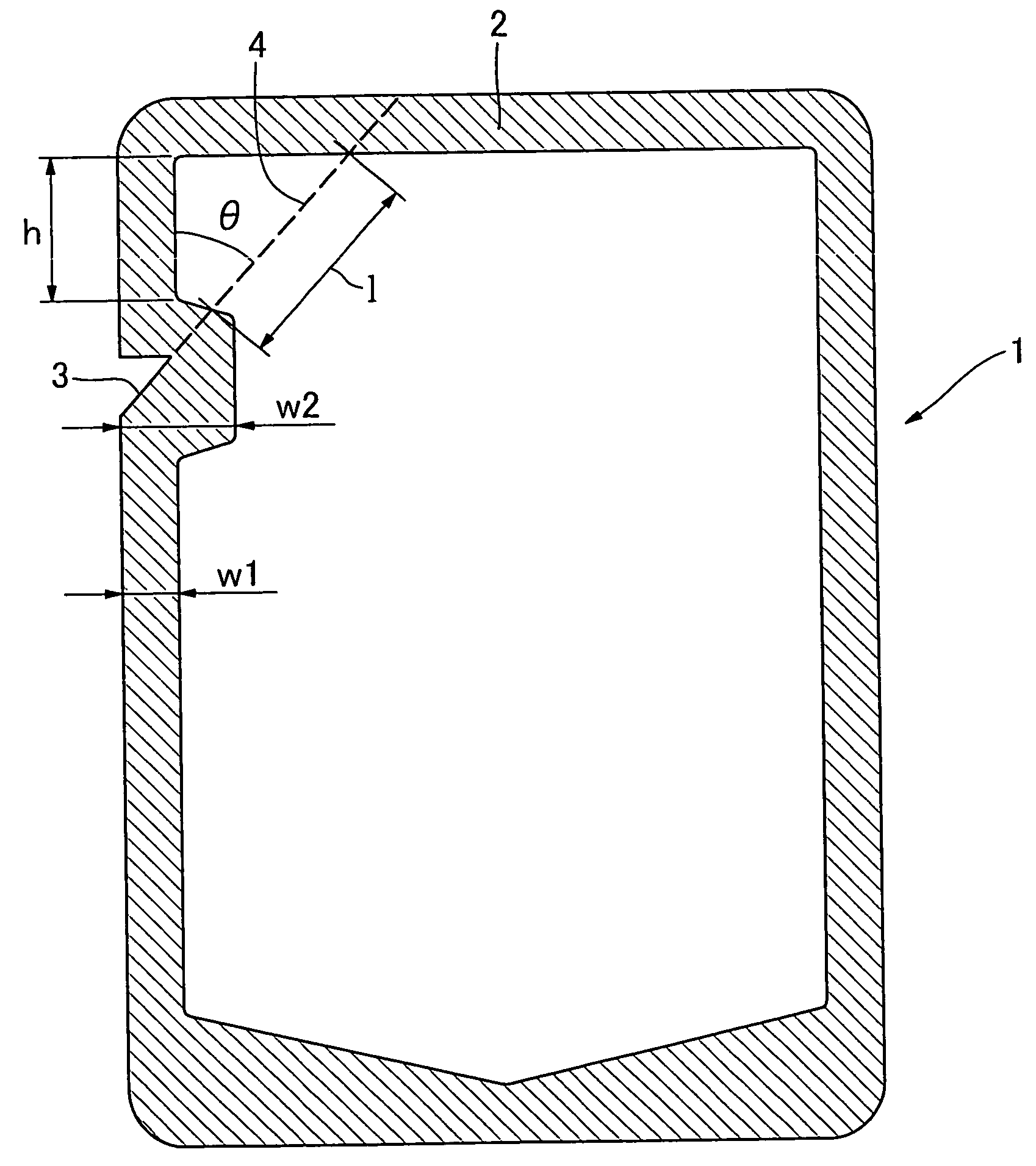
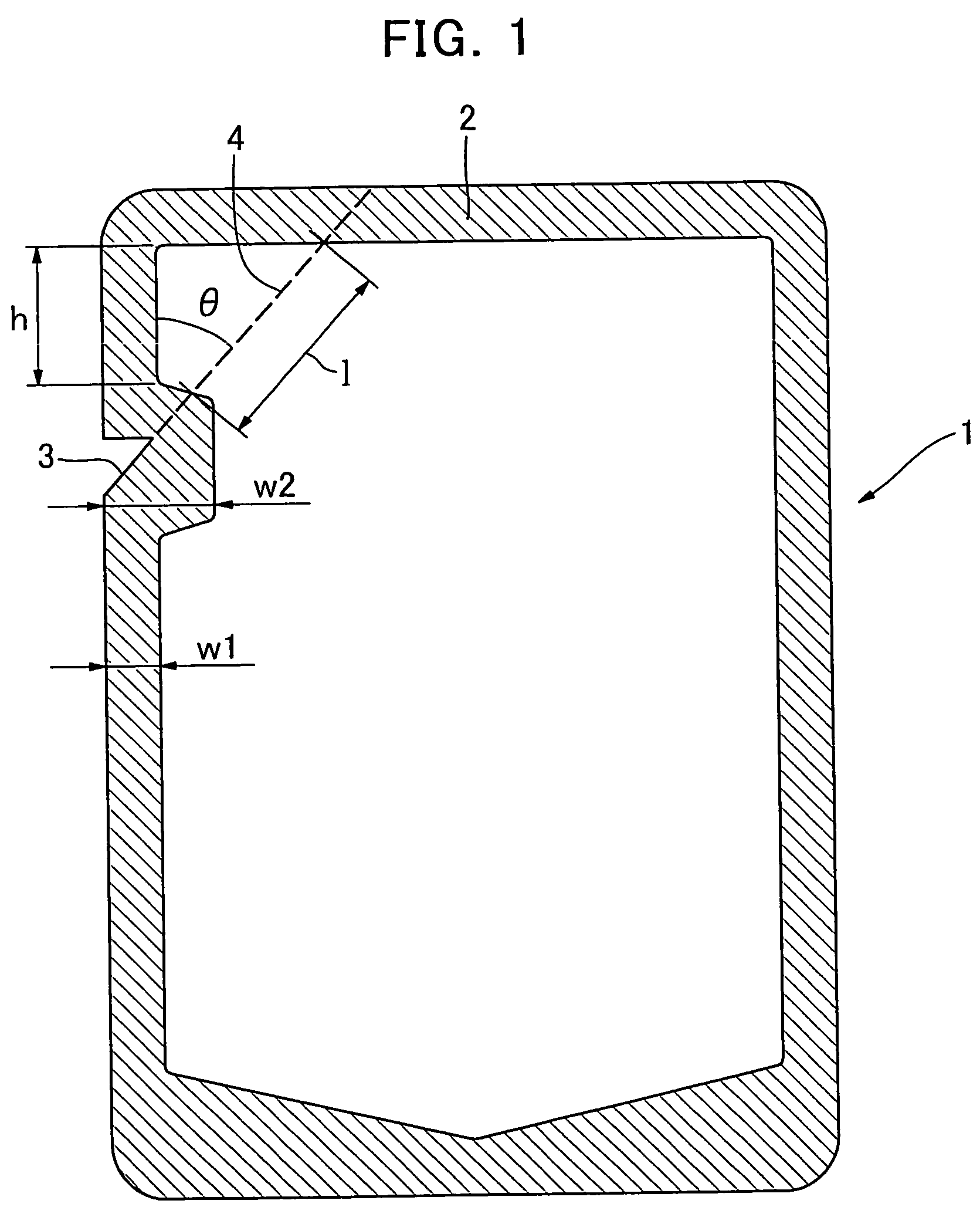
[0035] An oriented nylon film and a polyester film were laminated by dry-laminating on a four layer film produced by the method described in Japanese Patent Publication (JP Kokoku) No. Hei 1-54191, that is, an aluminum foil / a maleic anhydride modified polypropylene resin layer / an unmodified polypropylene resin layer / an ethylene propylene block copolymer in order to produce a metal laminated film consisting of a polyester film (thickness: 12 μm) / an urethane heat-hardening adhesive layer / an oriented nylon film (thickness: 15 μm) / an urethane heat-hardening adhesive layer / an aluminum foil (thickness: 7 μm) / a maleic anhydride modified polypropylene resin layer (thickness: 3 μm) / an unmodified polypropylene resin layer (thickness: 12 μm) / an ethylene propylene block copolymer (thickness: 60 μm). This metal laminated film was heat-sealed by its edges so that the ethylene propylene block copolymer became inside to produce a standing retort pouch 1 of FIG. 1. FIG. 1 shows a front vie...

Example

EXAMPLE 2

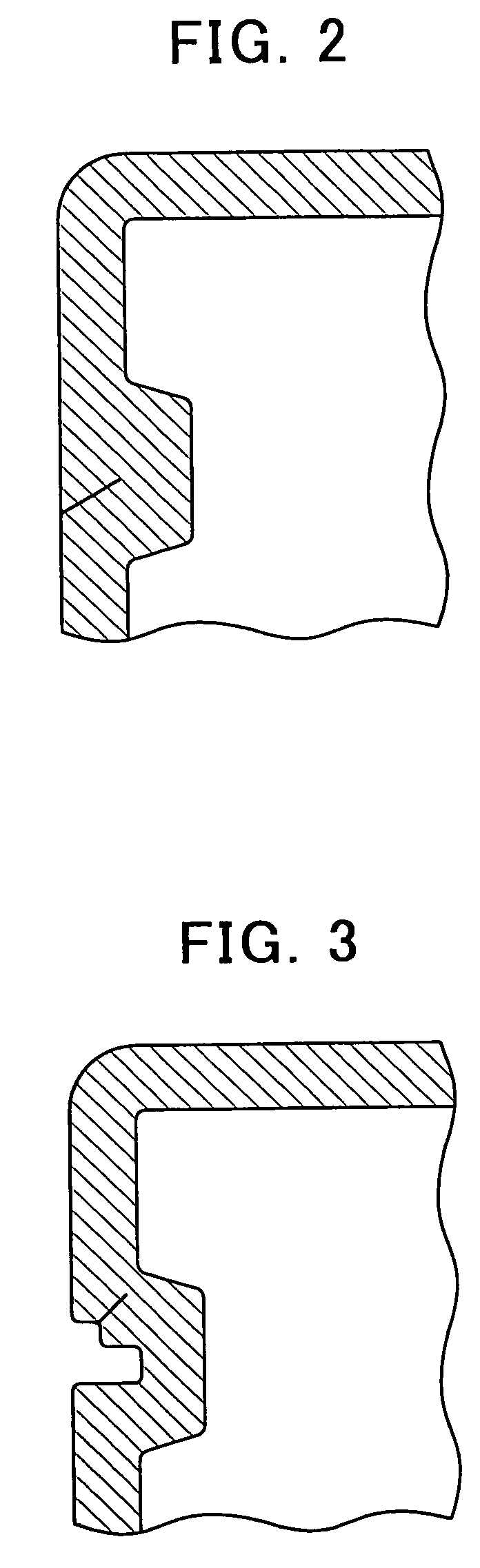
[0036] Using a metal laminated film laminated by dry-laminating, consisting of a polyester film (thickness: 12 μm) / an urethane heat-hardening adhesive layer / an oriented nylon film (thickness: 15 μm) / an urethane heat-hardening adhesive layer / an aluminum foil (thickness: 7 μm) / an urethane heat-hardening adhesive layer / an ethylene propylene block copolymer (thickness: 60 μm), the film was heat-sealed by its edges so that the ethylene propylene block copolymer became inside to produce Samples 4, 5 and 6, each of which had the same shape of the cutout (the notch) 3 for opening as that of Samples 1, 2 and 3, respectively.

Example

EXAMPLE 3

Sensory Evaluation

[0037] The sensory evaluation was conducted (5 panelists) on ease of obliquely opening and pouring ability into a cup using the standing retort pouches produced by Examples 1 and 2. The index of the ease of obliquely opening was based on extremely hard to open (−2), usual (0), and extremely easy to open (2). The index of the pouring ability into a cup was based on extremely hard to pour (−2), usual (0), and extremely easy to pour (2). Each were evaluated by 5 scale evaluation (−2, −1, 0, 1, 2).

[0038] The ease of obliquely opening of Sample 1 (0.7), Sample 2 (0.4) and Sample 3 (0.8) in Example 1 were better than that of Sample 4 (−1.6), Sample 5 (−1.5) and Sample 6 (−1.8) in Example 2.

[0039] The pouring ability into a cup of Sample 1 (0.7), Sample 2 (0.3) and Sample 3 (0.9) in Example 1 were better than that of Sample 4 (−0.6), Sample 5 (−0.4) and Sample 6 (−0.6) in Example 2. As a result of measuring the width of the opening of Samples 3 and 6, each av...


PUM

PropertyMeasurementUnit
Lengthaaaaaaaaaa
Thicknessaaaaaaaaaa
Thicknessaaaaaaaaaa

Abstract

The present invention provides a retort pouch which is made from a metal laminated film having the multilayer structure of a crystalline polypropylene resin film/an adhesive resin layer including a modified polypropylene/a metal foil/an adhesive layer/an oriented nylon film/an adhesive layer/a polyester film; and the retort pouch wherein a cutout for opening that is opening toward the side border is formed on the upper position of a heat-sealed part leaving some space from the superior border, an opening for pouring the contents is formed on the cut part by cutting the corner between the cutout and the superior border, and the opening is formed by cutting the corner along the line extending from the cutout for opening to the superior border at angles of 20 to 80 degrees to the side border. According to this retort pouch, the pouch is easy to open due to ease of tearing and does not easily lose the shape of the opening.

Description

TECHNICAL FIELD OF THE INVENTION [0001] The present invention relates to pouches for containing retort foods including fluid products such as liquids, powders and granular materials, and particularly including liquid diets and the like. Especially it relates to standing pouches. BACKGROUND OF THE INVENTION [0002] Recent years, standing pouches have been used as a container for storing flowable retort foods such as liquid diets. Such pouches are formed by use of strong laminated films that can maintain their configurations by themselves when contents are stored therein. In addition to the strength, the laminated films are required to have the properties such as retort resistance, the oxygen-barrier ability, and easiness of tearing which is a basis of easy-opening. [0003] As for such laminated films, for example, Japanese Patent Publication (JP Kokoku) No. Hei 1-54191 discloses a process for producing laminates for sealed and sterilized packages which comprises the steps of unifying a...

Claims


Application Information

Patent Timeline
IPC IPC(8): B32B27/32B65D30/08B65D75/00B65D75/58B65D81/34
CPCB65D31/02B65D75/008Y10T428/1334B65D81/34B65D75/5816
Inventor HARANO, SHIGENOBUSAGAE, MIHOMATSUMOTO, SHINICHIOMORI, MAYUMI
Owner AJINOMOTO CO INC
Why Eureka
Try Eureka