Power Supply Device and Wireless Communication System

a wireless communication and power supply technology, applied in transmission monitoring, electrical equipment casings/cabinets/drawers, instruments, etc., can solve the problems of long time for erecting and/or repairing, and achieve the effect of avoiding effective electromagnetic interference, reducing erecting and repairing time, and convenient reloading or resetting of wireless communication devices

Active Publication Date: 2010-03-25
UNIVERSAL SCIENTIFIC INDUSTRIAL (SHANGHAI) CO LTD
View PDF0 Cites 23 Cited by
  • Summary
  • Abstract
  • Description
  • Claims
  • Application Information

AI Technical Summary

Benefits of technology

[0013]The present exemplary embodiment employs the circuit frame of the power supply device including the decoder circuit and the signal strength indicator unit, and the corresponding circuit frame of the outdoor wireless communication device, such that the power supply device can display the signal receiving strength state of the outdoor wireless communication device. Therefore, the signal receiving strength state displayed on the power supply device may be a base for repairing men in the erecting and off-line or repairing process, such that the erecting and repairing time can be decreased. Furthermore, the signal receiving strength state displayed on the power supply device is prone to judge the current signal connecting state of the wireless communication device for the repairing men. In addition, the reset button is convenient to reload or reset the wireless communication device. The isolation circuit can avoid effectively the electromagnetic interference.

Problems solved by technology

Thus it will spend long time to finish erecting and / or repairing.

Method used


Image

  • Power Supply Device and Wireless Communication System
  • Power Supply Device and Wireless Communication System
  • Power Supply Device and Wireless Communication System

Examples


Embodiment Construction

[0019]Reference will now be made to the drawings to describe exemplary embodiments of the present power supply device, in detail. The following description is given by way of example, and not limitation.

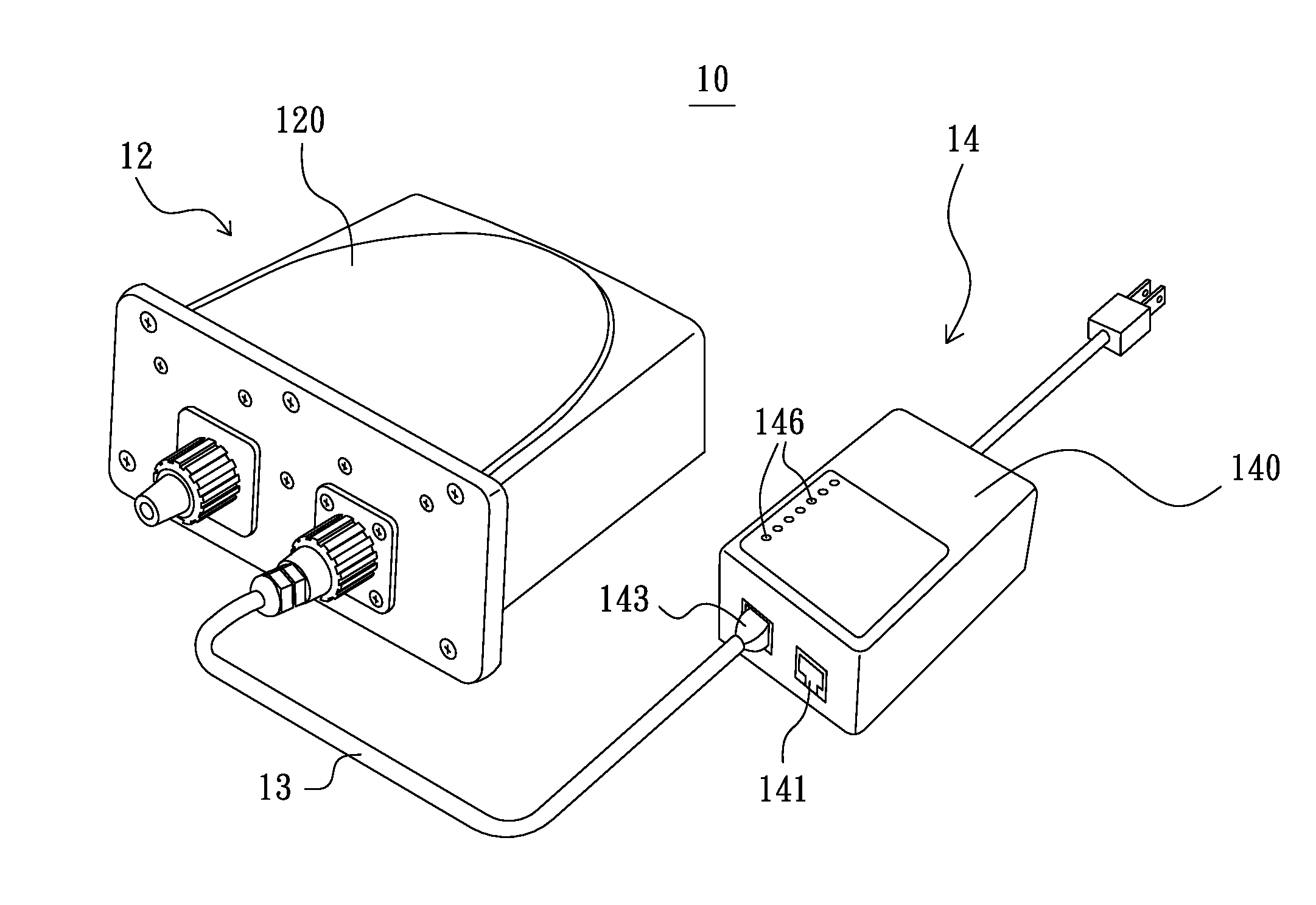
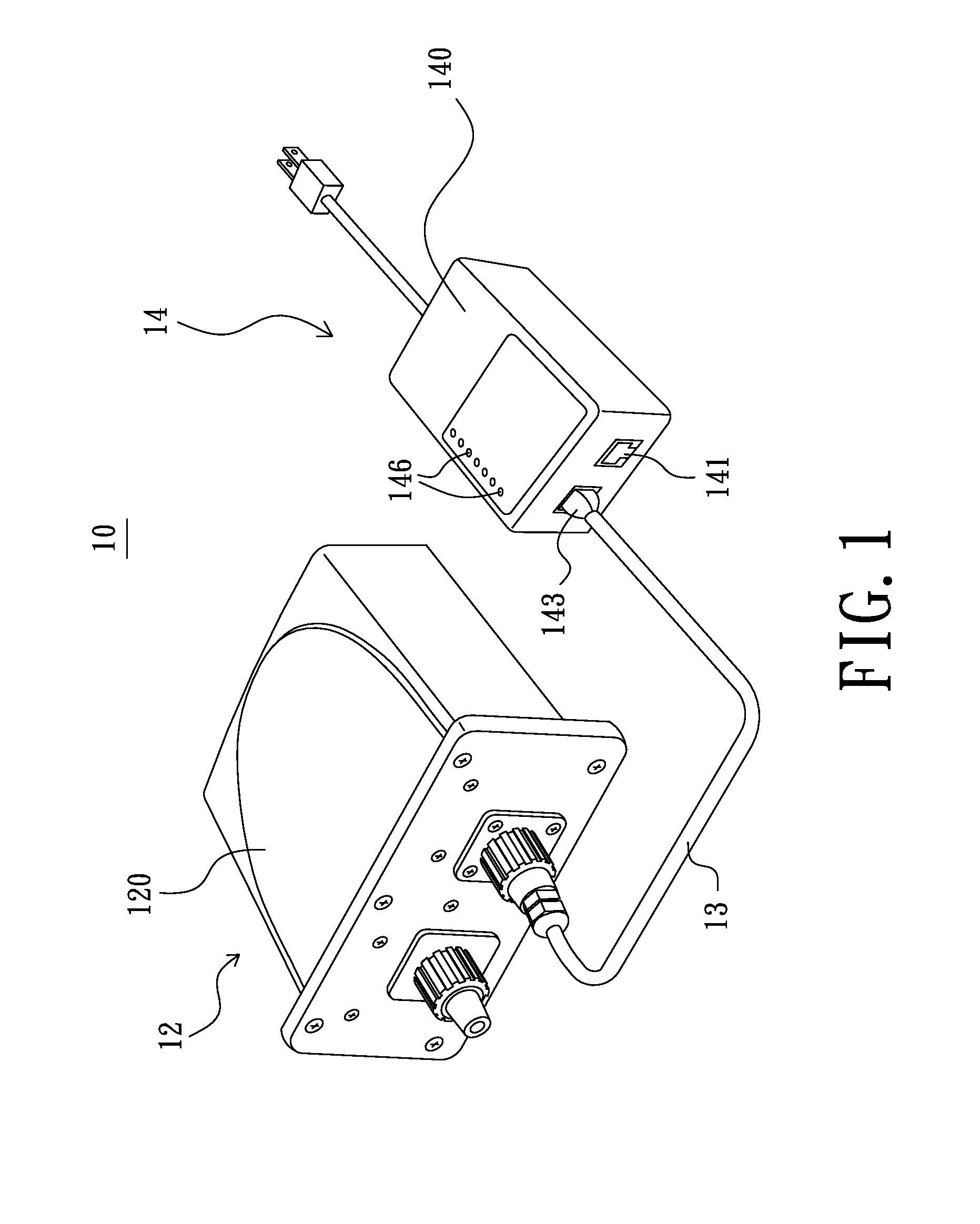
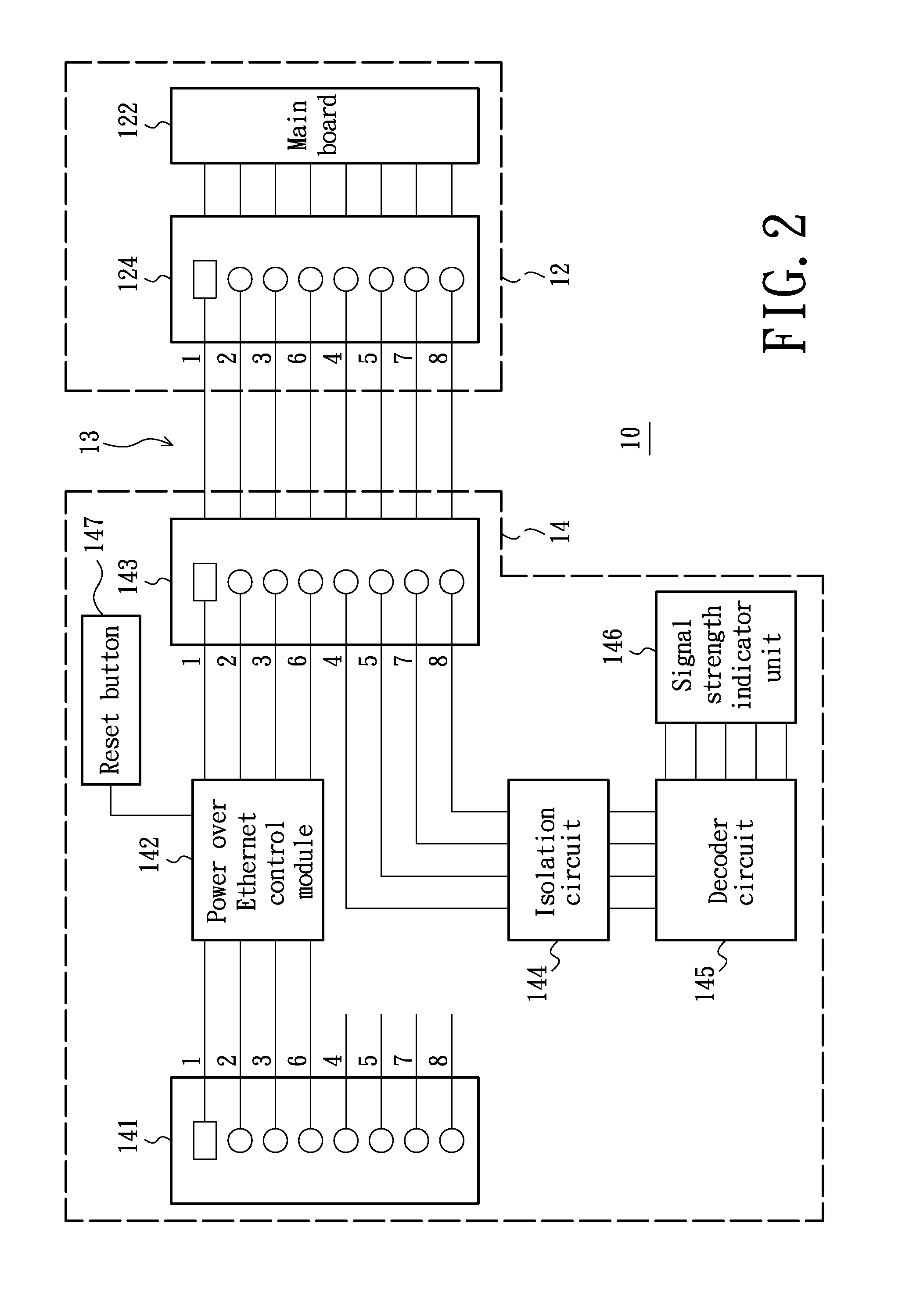
[0020]Referring to FIGS. 1-4, a wireless communication system in accordance with an exemplary embodiment of the present invention, is provided. The wireless communication system 10 includes a wireless communication device 12 and a power supply device 14. The wireless communication device 12 is generally arranged outdoors, and the power supply device 14 is configured for supplying power and data signals to the wireless communication device 12 via a network cable 13.

[0021]As shown in FIGS. 1 and 2, the wireless communication device 12 includes a shell 120, a main board 122 and a network port 124. The main board 122 is arranged in the shell 120. The network port 124 is connected to the main board 122, fixed on and exposed out of the shell 120. The network port 124 may be an Ethernet por...


PUM


Abstract

A power supply device and a wireless communication system are provided. The power supply device includes a data input port, a power over Ethernet control module, a network port, a decoder circuit and a signal strength indicator unit. The power over Ethernet control module is configured for receiving a data signal from the data input port to generate a data signal with power. The network port is configured for transmitting the data signal with power to the main board and receiving a signal in relation to a signal receiving strength state of the wireless communication device. The decoder circuit is connected to the network port and configured for generating a signal strength indicator signal. The signal strength indicator unit is connected to the decoder circuit and configured for receiving the signal strength indicator signal to display the signal receiving strength state of the wireless communication device.

Description

BACKGROUND[0001]1. Field of the Invention[0002]The present invention relates to the wireless communication technology field, and more specifically, to a power supply device and a corresponding wireless communication system.[0003]2. Description of the Related Art[0004]Currently, with the rapid development of the network, various wireless communication systems (for example, WiMax wireless communication system) adapted into the Ethernet to be as data transmission interfaces, are widely used. A conventional wireless communication system includes a power supply device and a wireless communication device (for example, wireless base station) under the 802.3af protocol. The power supply device includes an RJ-45 input port, a power over Ethernet control module, and an RJ-45 output port. The wireless communication device is generally arranged outdoors and connected to the RJ-45 output port via a network cable. The power over Ethernet control module is configured for receiving a data signal fr...

Claims


Application Information

Patent Timeline
Patent Type & Authority Applications(United States)
IPC IPC(8): G06F1/26
CPCH04L12/10
Inventor HUANG, CHIEN-HUAWANG, WEN-HUNGHUNG, YU-KUNCHIU, LI-CHI
Owner UNIVERSAL SCIENTIFIC INDUSTRIAL (SHANGHAI) CO LTD
Why Eureka
Try Eureka