Liquid droplet ejecting apparatus and method of controlling liquid droplet ejecting apparatus

a technology of liquid droplet ejection and liquid droplet ejection, which is applied in the direction of printing, other printing apparatus, etc., can solve the problems of inability to quickly raise the pressure acting on the recording head, the flow velocity of ink inside the flow path cannot be sufficiently discharged from the nozzle, and the air bubbles and contaminants included in the ink inside the flow path cannot be sufficiently discharged

Active Publication Date: 2010-04-01
FUJIFILM CORP
View PDF2 Cites 79 Cited by
  • Summary
  • Abstract
  • Description
  • Claims
  • Application Information

AI Technical Summary

Benefits of technology

[0026]According to the present invention, there is obtained the effect that the ability of a liquid droplet eject

Problems solved by technology

However, in the technology disclosed in JP-A No. 2007-223278, there has been the problem that, in the ink supply system that includes the intermediate tank, when the flow path that is communicated with the recording head is pressurized, air bubbles and contaminants included in the ink inside the flow path cannot be sufficiently discharged from the nozzles because, as indicated by graph A in FIG. 13, the pressure acting on the recording head cannot be quickly raised.
Further, there has also been the problem that, in the

Method used


Image

  • Liquid droplet ejecting apparatus and method of controlling liquid droplet ejecting apparatus
  • Liquid droplet ejecting apparatus and method of controlling liquid droplet ejecting apparatus
  • Liquid droplet ejecting apparatus and method of controlling liquid droplet ejecting apparatus

Examples


first embodiment

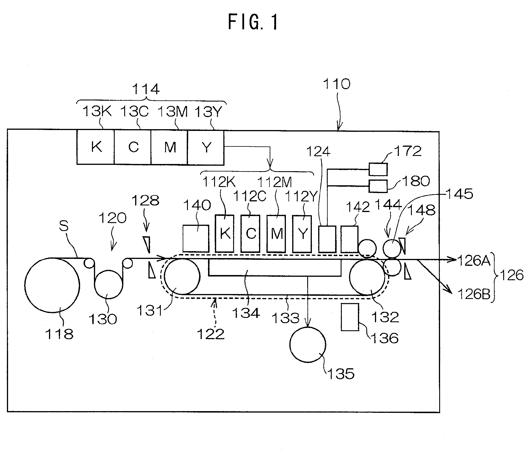
[0042]In FIG. 1, there is shown an overall configural diagram of an inkjet recording apparatus 110 that represents one embodiment of a liquid droplet ejecting apparatus of the present invention. As shown in FIG. 1, the inkjet recording apparatus 110 is equipped with: plural inkjet recording heads (hereinafter called “heads”) 112K, 112C, 112M and 112Y (hereinafter also collectively called a “printing unit 112” when it is not necessary to distinguish by color) that are disposed in correspondence to black (K), cyan (C), magenta (M) and yellow (Y) inks; an ink storing / charging unit 114 that stores the inks supplied to the heads 112K, 112C, 112M and 112Y; a paper supplying unit 18 that supplies recording paper S as a recording medium; a decurling unit 120 that decurls the recording paper S; a belt conveyance unit 122 that is disposed facing a nozzle surface (an ink ejection surface) of the printing unit 112 and conveys the recording paper S while preserving the planarity of the recording...

second embodiment

[0121]Next, a second embodiment will be described. The configuration of the inkjet recording apparatus pertaining to the second embodiment is the same as that of the inkjet recording apparatus 110 pertaining to the first embodiment, so description thereof will be omitted here.

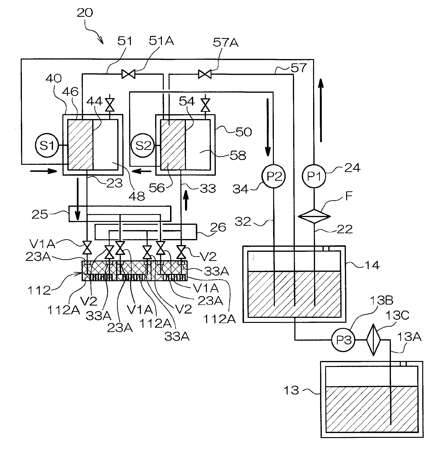
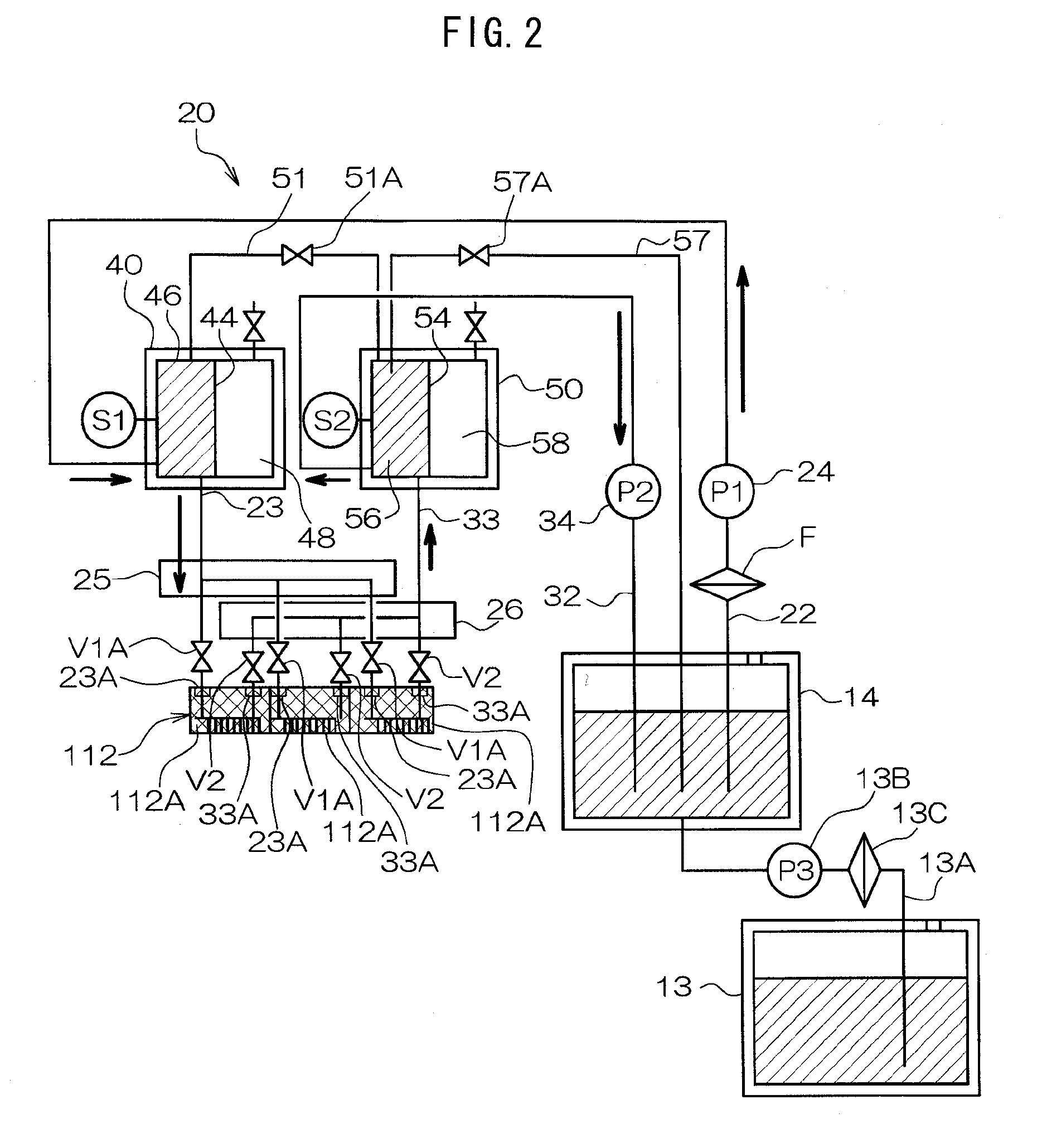
[0122]Next, the action of the inkjet recording apparatus 110 when pressurized discharge processing pertaining to the second embodiment is executed will be described with reference to FIG. 11. FIG. 11 is a flowchart showing a flow of processing by a pressurized discharge processing program that is executed by the system controller 64 at that time. This program is stored beforehand in a predetermined region of the ROM 68. Further, here, in order to avoid confusion, a case will be described where the gas chamber valves 49V and 59V are open and where the supply-use valves V1A, the recovery-use valves V2, the third flow path-use valve 57A and the fourth flow path-use valve 51A are closed.

[0123]In step 300 of FIG. 11...


PUM


Abstract

A liquid droplet ejecting apparatus includes: a supply-use tank that is sectioned by an elastic film into a liquid chamber and a gas chamber; a supply-use flow path that interconnects the supply-use tank and a recording head; and a pump that pumps the liquid stored in the liquid chamber to the recording head via the supply-use flow path by supplying the liquid from an external tank to the liquid chamber of the supply-use tank. The flow path is controlled to supply the liquid to the liquid chamber in a state where the supply-use flow path is closed, cause the elastic film to press against an inner wall of the gas chamber, thereafter open the supply-use flow path, release the elastic film from the pressing state, and supply, with the pump, the liquid from the external tank to the recording head via the supply-use tank and the supply-use flow path.

Description

CROSS-REFERENCE TO RELATED APPLICATION[0001]This application claims priority under 35 USC 119 from Japanese Patent Application No. 2008-254625 filed on Sep. 30, 2008, the disclosure of which is incorporated by reference herein.BACKGROUND OF THE INVENTION[0002]1. Field of the Invention[0003]The present invention relates to a liquid droplet ejecting apparatus and a method of controlling the liquid droplet ejecting apparatus.[0004]2. Description of the Related Art[0005]Conventionally, liquid droplet ejecting apparatus that eject ink droplets from nozzles of an inkjet recording head (also called a “recording head” below) to record an image on a recording medium such as recording paper have been known. Usually, the ink is supplied to the recording head via a supply-use flow path from an ink tank in which the ink is stored.[0006]Contaminants such as dirt and dust that become mixed into the ink and air bubbles that form in the ink cause ejection defects and increase flow path resistance, a...

Claims


Application Information

Patent Timeline
IPC IPC(8): B41J2/175
CPCB41J2/175B41J29/38B41J2/17596B41J2/17513
Inventor KATADA, MASAHITOKATADA, YUKOKATADA, NATSUKIKATADA, DAICHI
Owner FUJIFILM CORP
Why Eureka
Try Eureka