Multi-function circuit interruption accessory

a multi-functional, accessory technology, applied in the direction of switches operated by excess current, switches operated by falling voltage, electrical equipment, etc., can solve the problems of many circuit breakers becoming crowded, complicated, and expensive, and overcome the obstacles to doing so

Inactive Publication Date: 2010-04-01
GENERAL ELECTRIC CO
View PDF11 Cites 6 Cited by
  • Summary
  • Abstract
  • Description
  • Claims
  • Application Information

AI Technical Summary

Problems solved by technology

Many users opt for both ST and UVR that many circuit breakers become crowded, more expensive, and more complicated.
Thus, while there is a need for a combined ST and LVR accessories for a circuit breaker, there are obstacles to doing so that must be overcome.

Method used


Image

  • Multi-function circuit interruption accessory
  • Multi-function circuit interruption accessory
  • Multi-function circuit interruption accessory

Examples


Embodiment Construction

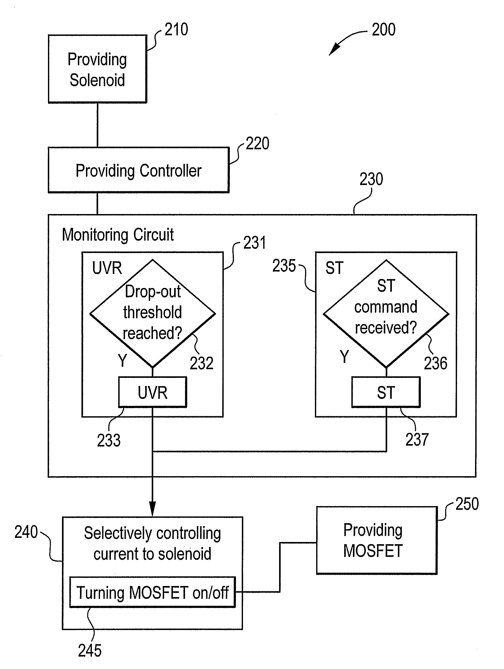
[0010]With reference to the accompanying Figures, examples of an apparatus and method according to embodiments disclosed herein are shown. For purposes of explanation, numerous specific details are shown in the drawings and set forth in the detailed description that follows in order to provide a thorough understanding of embodiments of the present invention. It will be apparent, however, that embodiments of the present invention may be practiced without these specific details. In other instances, well-known structures and devices are schematically shown in order to simplify the drawing.

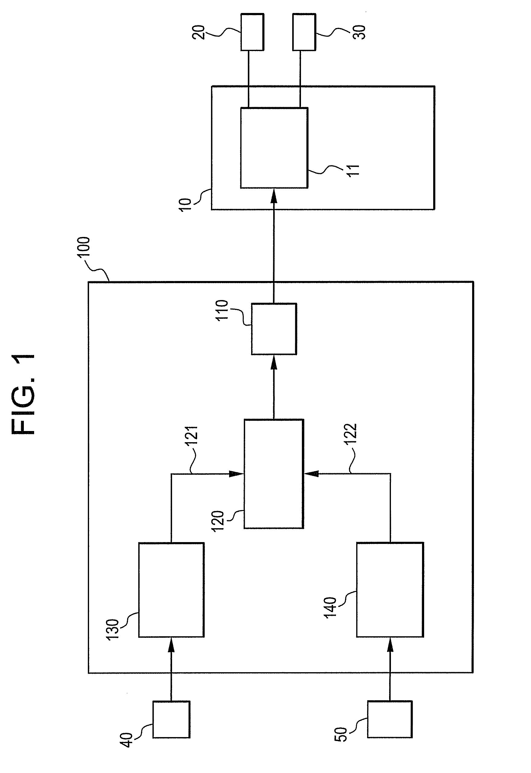
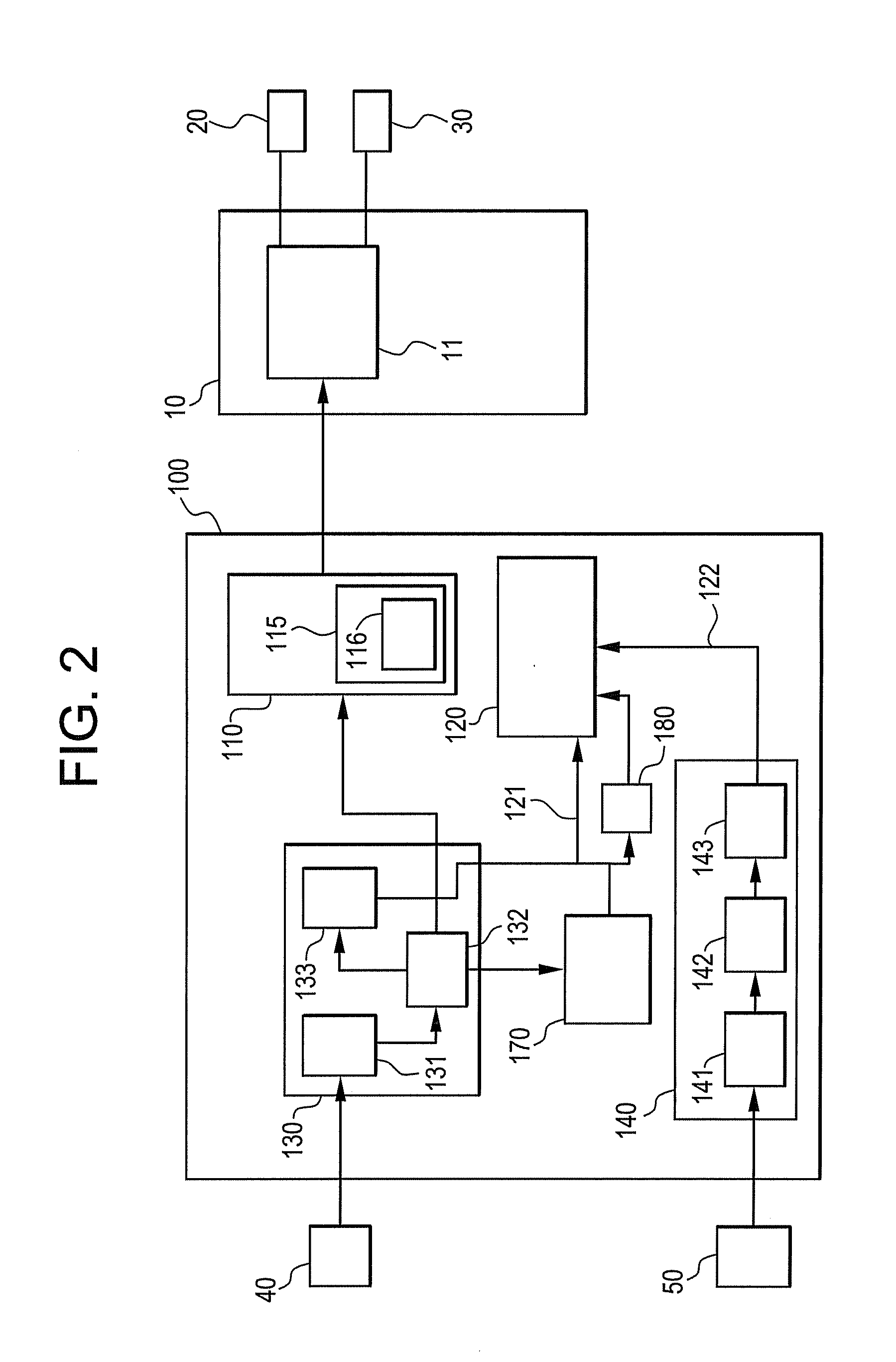
[0011]In FIG. 1, a combined shunt trip and undervoltage protection apparatus 100 has a solenoid 110 disposed and configured to operate a mechanism 11 of a circuit interruption device or circuit breaker 10 in a circuit to be protected. The breaker 10 is situated between a line conductor 20 and a load conductor 30 to selectively provide a connection between line and load. The connection is made between ...


PUM


Abstract

A protection apparatus for a circuit breaker disposed in a circuit to be protected uses a solenoid configured to operate the circuit breaker on command, an undervoltage release (UVR) sensing apparatus configured to produce an UVR signal in response to a line voltage of the circuit to be protected falling below a predetermined level, and a shunt trip (ST) sensing apparatus configured to produce a ST signal when it senses a ST command. A controller operably connected to the UVR sensing apparatus, the ST sensing apparatus, and the solenoid, is configured to receive the UVR and ST signals when produced and controls the solenoid to open the breaker in response to receipt by the controller of either of the UVR and ST signals.

Description

BACKGROUND[0001]Embodiments of the invention disclosed herein relate to circuit interruption devices that protect electrical equipment. In particular, embodiments of the invention relate to shunt trip and undervoltage release accessories for circuit breakers.[0002]A shunt trip (ST) device, used to open a remote circuit breaker, and an under voltage release (UVR) device, used to protect the circuit in which the circuit breaker is present from a low voltage condition, are two available accessories for a circuit breaker. Currently, a separate accessory is required for each of the ST and LVR devices in a circuit breaker, each one having their own housings, their own electronics, and their own separate solenoids. Many users opt for both ST and UVR that many circuit breakers become crowded, more expensive, and more complicated.[0003]Though both ST and TVR open a breaker using solenoids, UVR solenoids are maintained in an on state until line voltage goes below a predetermined minimum level...

Claims


Application Information

Patent Timeline
Patent Type & Authority Applications(United States)
IPC IPC(8): H01H47/00
CPCH01H83/12H01H2083/203H01H83/20H01H71/00
Inventor ANAND, PRADEEP KUMAR
Owner GENERAL ELECTRIC CO
Why Eureka
Try Eureka