Marking device docking stations having security features and methods of using same

a technology of security features and marking devices, which is applied in the direction of battery/fuel cell control arrangement, electric apparatus casings/cabinets/drawers, instruments, etc., can solve the problems of mishandling of marking devices, broken marking devices, and insignificant cost of individual marking devices by users

Active Publication Date: 2010-04-08
CERTUSVIEW TECH LLC
View PDF101 Cites 213 Cited by
  • Summary
  • Abstract
  • Description
  • Claims
  • Application Information

AI Technical Summary

Benefits of technology

This patent describes a special platform that can hold a marker device used to indicate the location of underground facilities during construction. It has a mechanical holder, an electrical connection, and controls how it operates. Its purpose is to make it easier and more efficient to locate these markers on-site.

Problems solved by technology

The technical problem addressed in this patent text relates to improving how marking devices (such as spray pain) are handled and managed in the field, particularly with increasing complexity and costs. Additionally, there is an issue of securely storing marking devices in vehicles to prevent accidents.

Method used


Image

  • Marking device docking stations having security features and methods of using same
  • Marking device docking stations having security features and methods of using same
  • Marking device docking stations having security features and methods of using same

Examples


Embodiment Construction

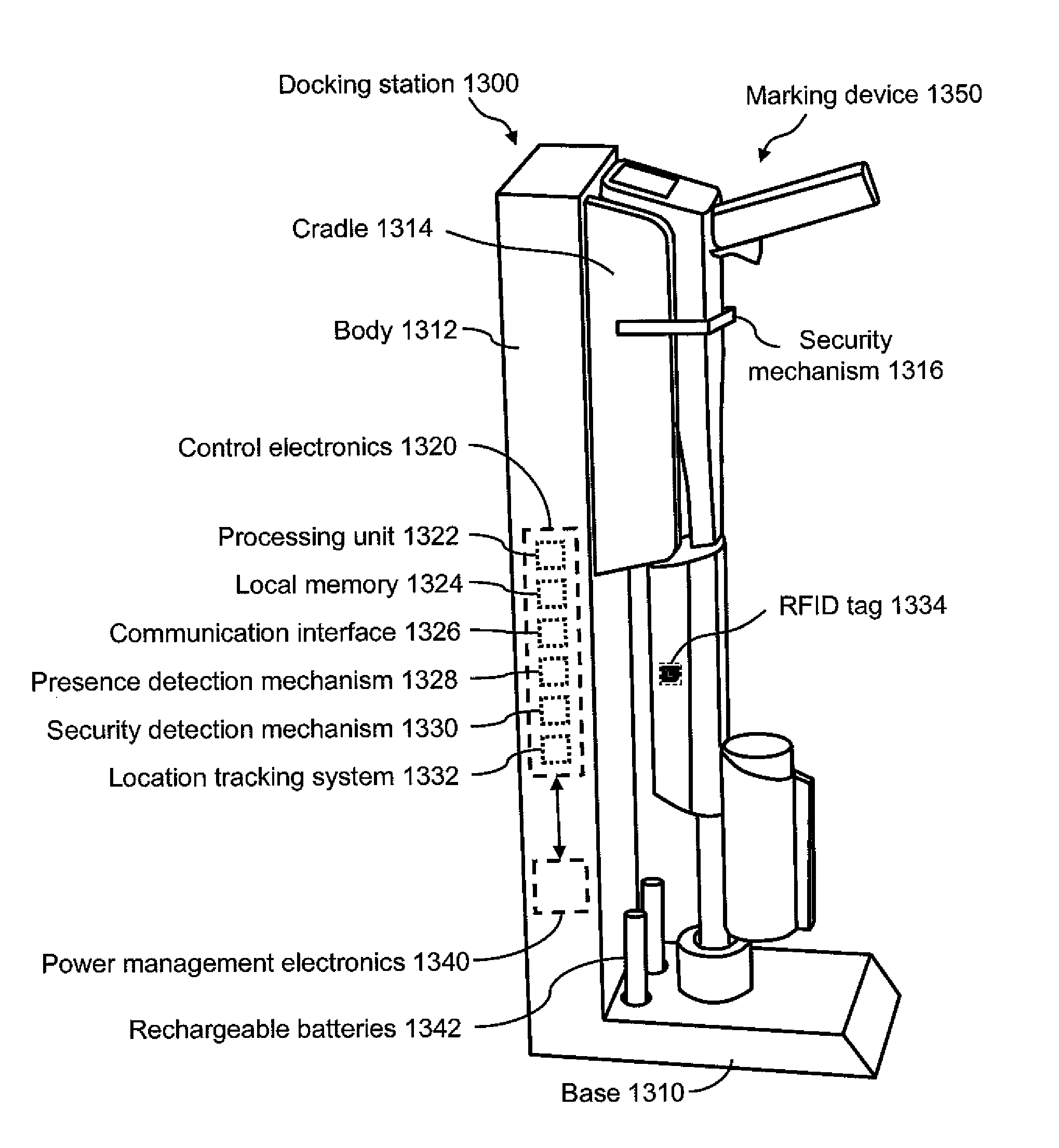
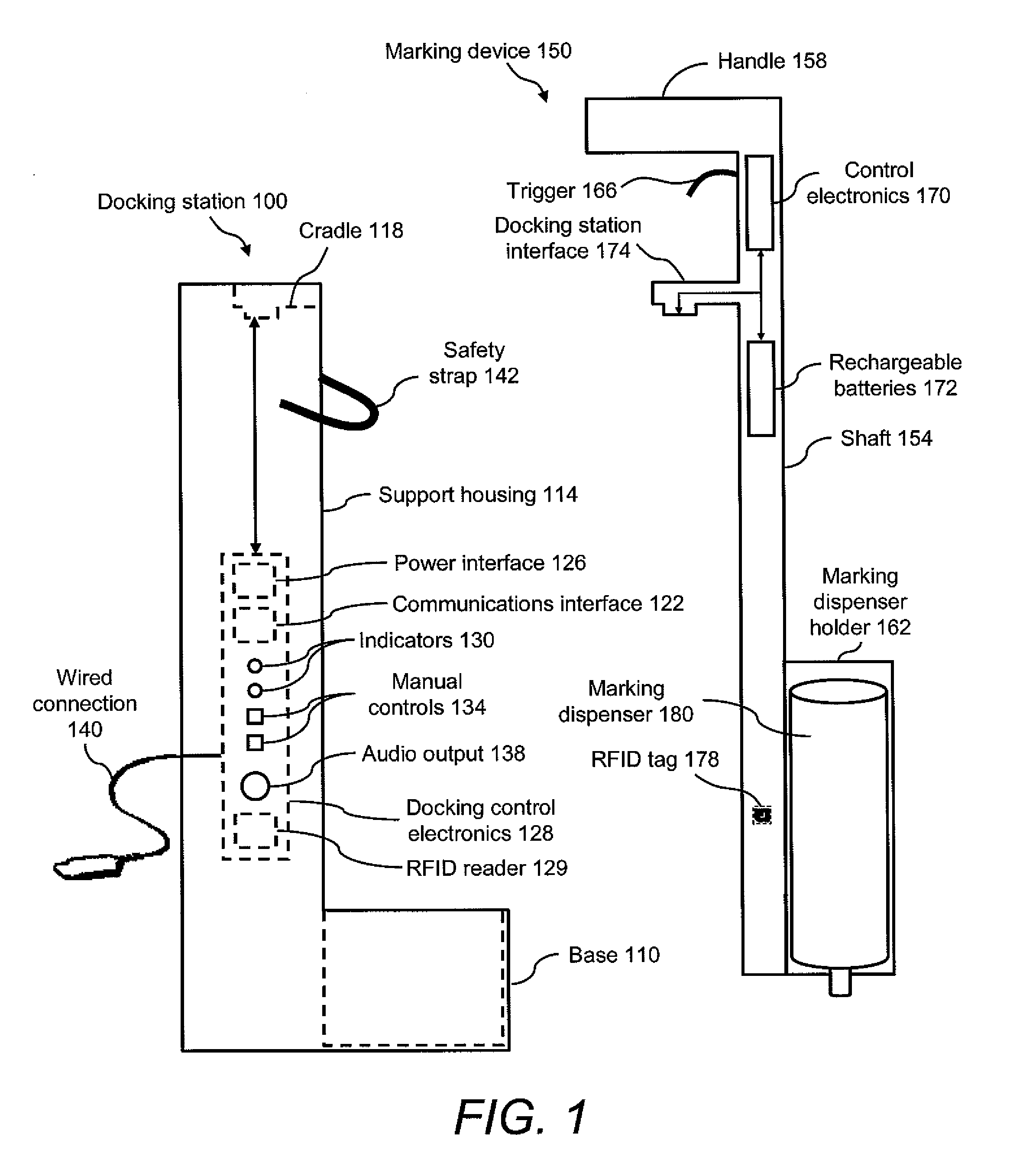
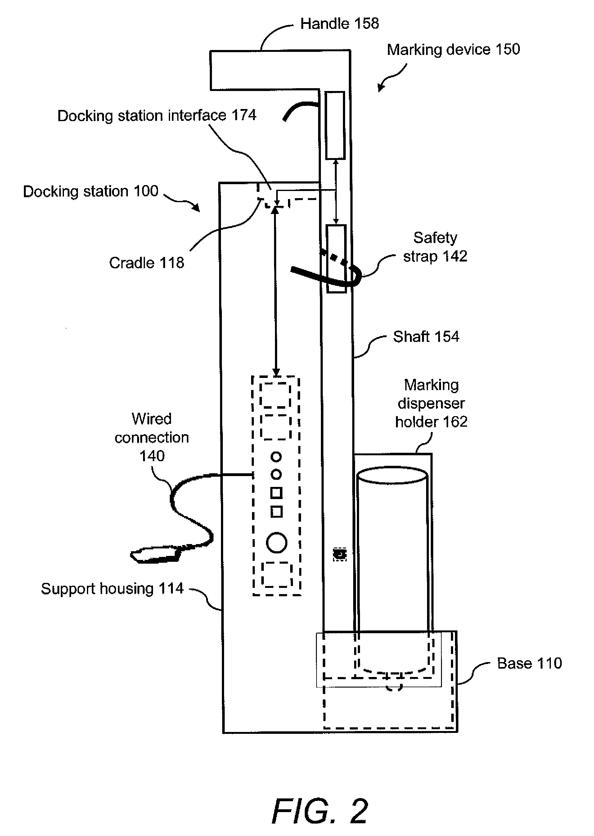
[0039]The present invention relates to marking devices used for marking the presence or absence of an underground facility in a dig area and, more particularly, to docking stations for use with such marking devices. The present invention further includes methods for using docking stations with marking devices. By way of example, the docking station may serve as a home base for storage of a marking device and for charging the battery of a marking device. In some embodiments, the docking station may be a mobile docking station that is installed in a vehicle. In other embodiments, the docking station may be a fixed docking station that is installed at a central location in the field, at a central office, at a home base facility, and the like. The docking station may be used in a variety of locations that are convenient and / or accessible for a user, including worksites, and may be fixed or mobile depending on the configuration.

[0040]For purposes of the present disclosure, the term “dig ...


PUM


Abstract

Docking stations and docking methods are provided for use with marking devices used for marking the presence or absence of an underground facility in a dig area. The docking station may serve as a home base for storage of a marking device, for charging the battery of a marking device, for transferring data to and from a marking device, and for securing a marking device against unauthorized use and/or theft. The docking station may be a mobile docking station that is installed in a vehicle or may be a fixed docking station that is installed at a central location in the field, at a central office, at a home base facility, and the like.

Description


Claims


Application Information

Patent Timeline
Owner CERTUSVIEW TECH LLC
Why Eureka
Try Eureka