
Service and diagnostic tool for HVAC systems

Active Publication Date: 2005-07-21
CARRIER CORP
View PDF13 Cites 218 Cited by
  • Summary
  • Abstract
  • Description
  • Claims
  • Application Information

AI Technical Summary

Benefits of technology

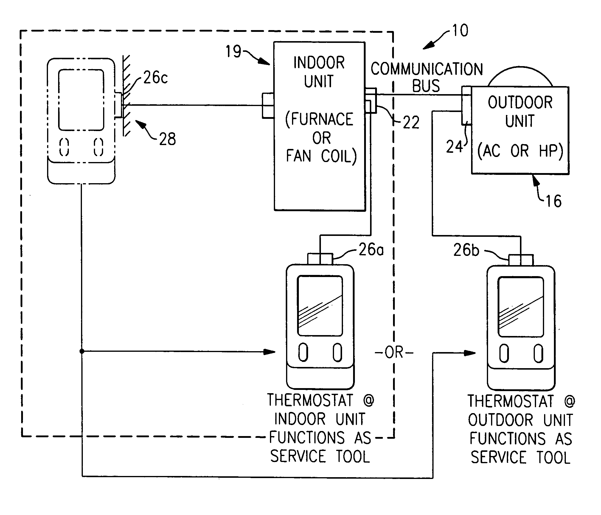
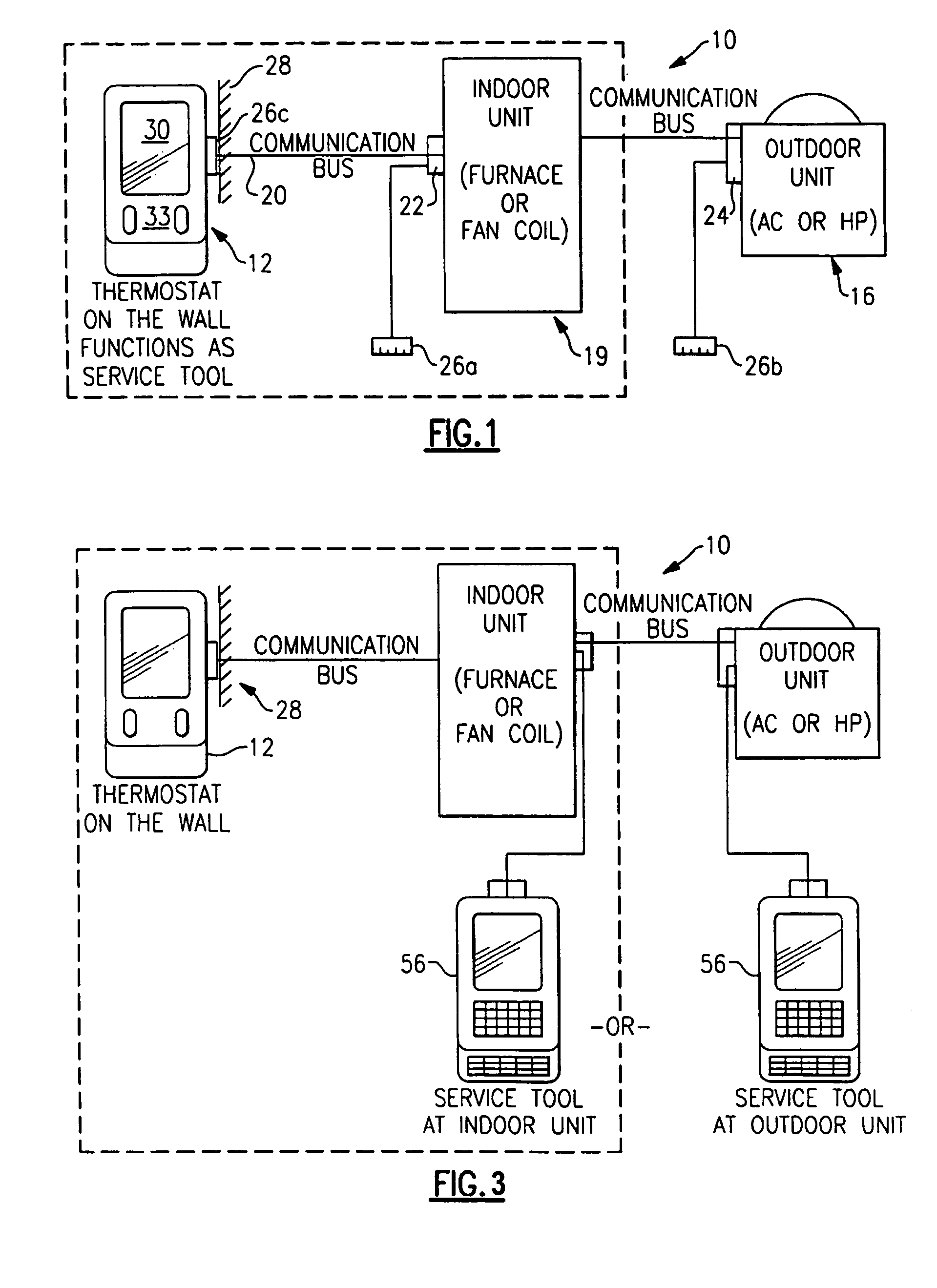
[0010] While the system-wide functions may be accomplished by selectively moving the portable controller unit without a separate service tool, the system permits a service tool to be connected to any of the docking stations to which the portable controller unit may be connected for added convenience and flexibility. An additional benefit of this is that the technician need not enter the structure in which the HVAC system is installed.

Problems solved by technology

Also, the information provided by such conventional art components is limited to the single component to which the diagnostic unit is connected and not the entire system.
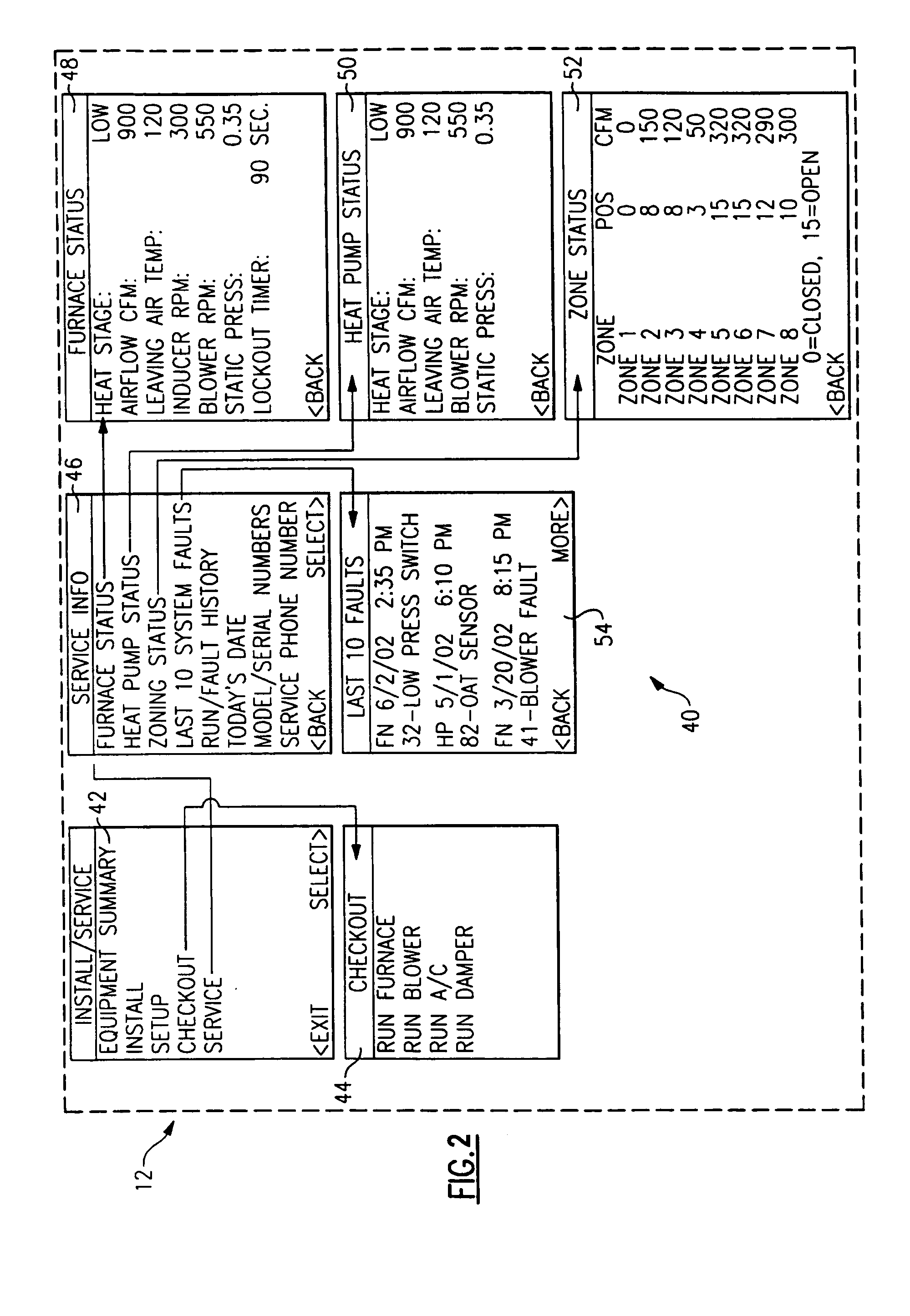
There is no conventional way to directly command a specific stage of heating or cooling, and, in many cases, a technician must wait for the various protection and staging timers to time out before the desired operating mode is activated.
Although effective, conventional service techniques may make the task of the service technician more difficult and time consuming, which may lead to improper installation or incorrect diagnosis.

Method used


Image

  • Service and diagnostic tool for HVAC systems
  • Service and diagnostic tool for HVAC systems
  • Service and diagnostic tool for HVAC systems

Examples


Embodiment Construction

[0018]FIG. 1 illustrates a schematic view of an HVAC system 10. The system 10 generally includes a portable controller unit 12 which communicates with an indoor HVAC component 14 and an outdoor HVAC component 16. The components 14, 16 preferably communicate with the portable controller unit 12 over a digital communication bus 20. The bus 20 preferably includes four communication paths such as four paths or the like which communicate data and power. It should be understood that other communication systems will likewise benefit from the present invention.

[0019] The indoor component 14 includes an indoor unit microprocessor controller 22 that communicates with the portable controller unit 12 over the bus 20. The indoor component 14 typically includes a furnace, fan coil, or the like. The outdoor component 16, such as an A / C unit or heat pump, includes an outdoor unit microprocessor controller 24 that communicates with the portable controller unit 12 over the bus 20. That is, each HVAC...


PUM


Abstract

An HVAC system includes a portable controller unit which communicates with an indoor HVAC component and an outdoor HVAC component over a digital communication bus. A multiple of docking stations each in communication with the data bus are located at a multiple of locations throughout the system such that the portable controller unit may be selectively connected to any of the ports and moved therebetween. By moving the portable controller unit, the technician is then physically present at the HVAC component while exercising the system to obtain additional information and measurements directly from the HVAC component.

Description

[0001] The present application claims priority to U.S. Provisional Patent Application Ser. No. 60 / 537532, filed Jan. 7, 2004. The disclosure of this provisional application is incorporated herein in its entirety, by reference.BACKGROUND OF THE INVENTION [0002] The present invention relates to an HVAC system, and more particularly to a service and diagnostic tool, which communicates with the entire HVAC system from a multiple of locations. [0003] A heating, ventilating, and air conditioning (HVAC) system includes multiple components that function together in a coordinated manner. Typically, an HVAC system includes an indoor unit such as a gas furnace or fan coil, an outdoor unit such as an A / C or heat pump, and a thermostat. More sophisticated systems might include a multi-zone control capacity with zone control and zone dampers. HVAC systems also frequently include subsystems such as filters, humidifiers, and ventilators. [0004] In conventional residential HVAC systems, minimal info...

Claims


Application Information

Patent Timeline
IPC IPC(8): G05B23/02
CPCG05B2219/2642G05B15/02G01M1/30G05B13/00G05B21/00
Inventor SHAH, RAJENDRA K.PURANEN, CHRIS
Owner CARRIER CORP
Learn More