Dental hygiene device

a dental hygiene and device technology, applied in the field of dental hygiene devices, can solve the problems of disadvantages of prior art devices, no widespread use or commercial success,

Inactive Publication Date: 2006-07-25
KLUPT MICHAEL
View PDF28 Cites 225 Cited by
  • Summary
  • Abstract
  • Description
  • Claims
  • Application Information

AI Technical Summary

Benefits of technology

[0036]The first fluid conduit which may be a flexible non-distensible tubing is formed from or incorporates the bundled optically transmissive filaments. Thus, the first fluid conduit may be a flexible non-distensible optically transmissive cylinder containing a moving fluid which is pumped out of the telescoping handle chamber and delivered under pressure from the fluid outlet nozzle. In such a case, the illumination head projects a cross-sectional ring of light around the fluid stream permitting the user to visually monitor the effectiveness of the dental hygiene procedure.
[0043]An important objective of the present invention is to provide a dental hygiene device which requires minimal amount of maintenance by the user.
[0045]Another object of the present invention is to provide in a unitary dental hygiene device a system which replaces a plurality of dental hygiene implements such as a toothbrush and an irrigation device as well as to help a user to visually identify dental areas that may need increased care and attention as disclosed by the illumination provided.
[0046]Another object of the subject invention is to provide a dental hygiene system wherein the refilling of the handle chamber with fluid from a reservoir can be accomplished automatically, efficiently, and economically.

Problems solved by technology

None has seen widespread use or commercial success reflecting the more or less inelegant means chosen to design such prior art devices.
Other toothbrush systems with a handle reservoir include U.S. Pat. No. 6,669,390; and U.S. Pat. No. 6,575,203, however, such prior art devices include disadvantages as previously referred to above.

Method used


Image

  • Dental hygiene device
  • Dental hygiene device
  • Dental hygiene device

Examples


Embodiment Construction

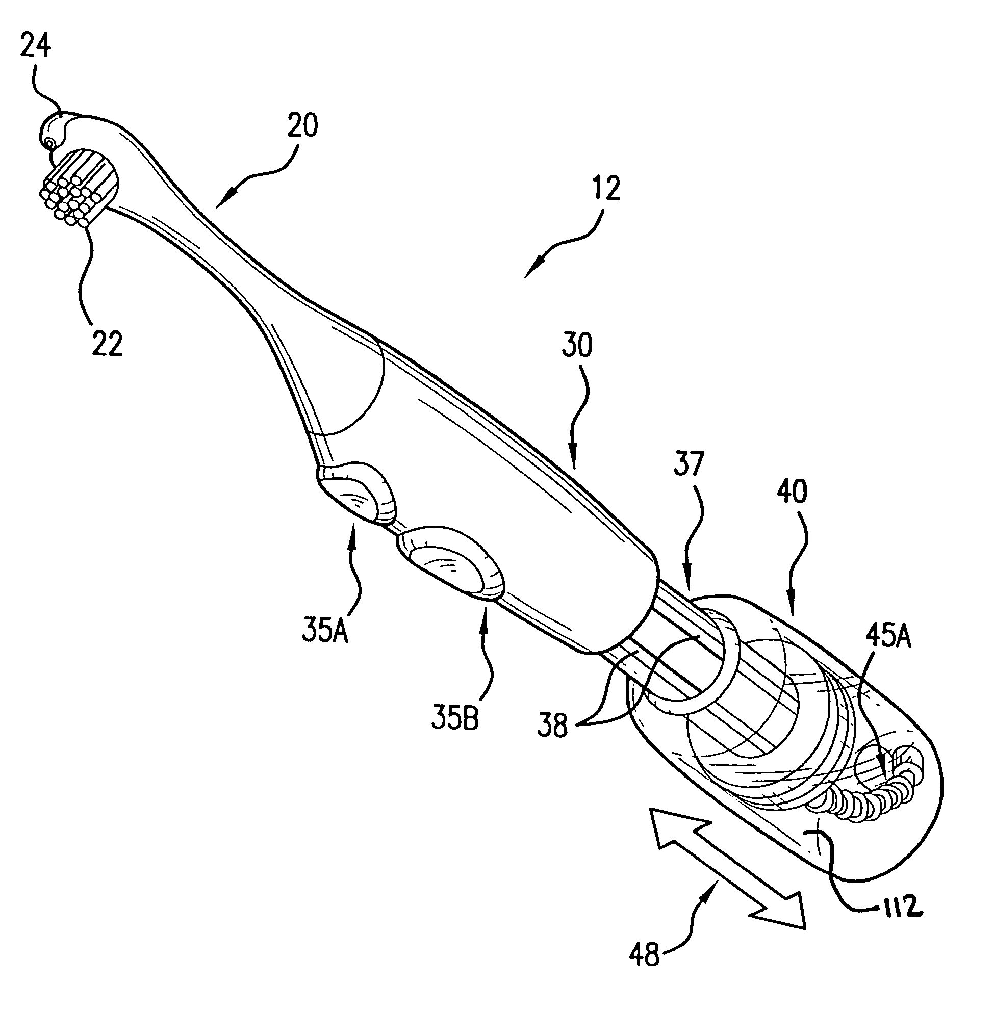
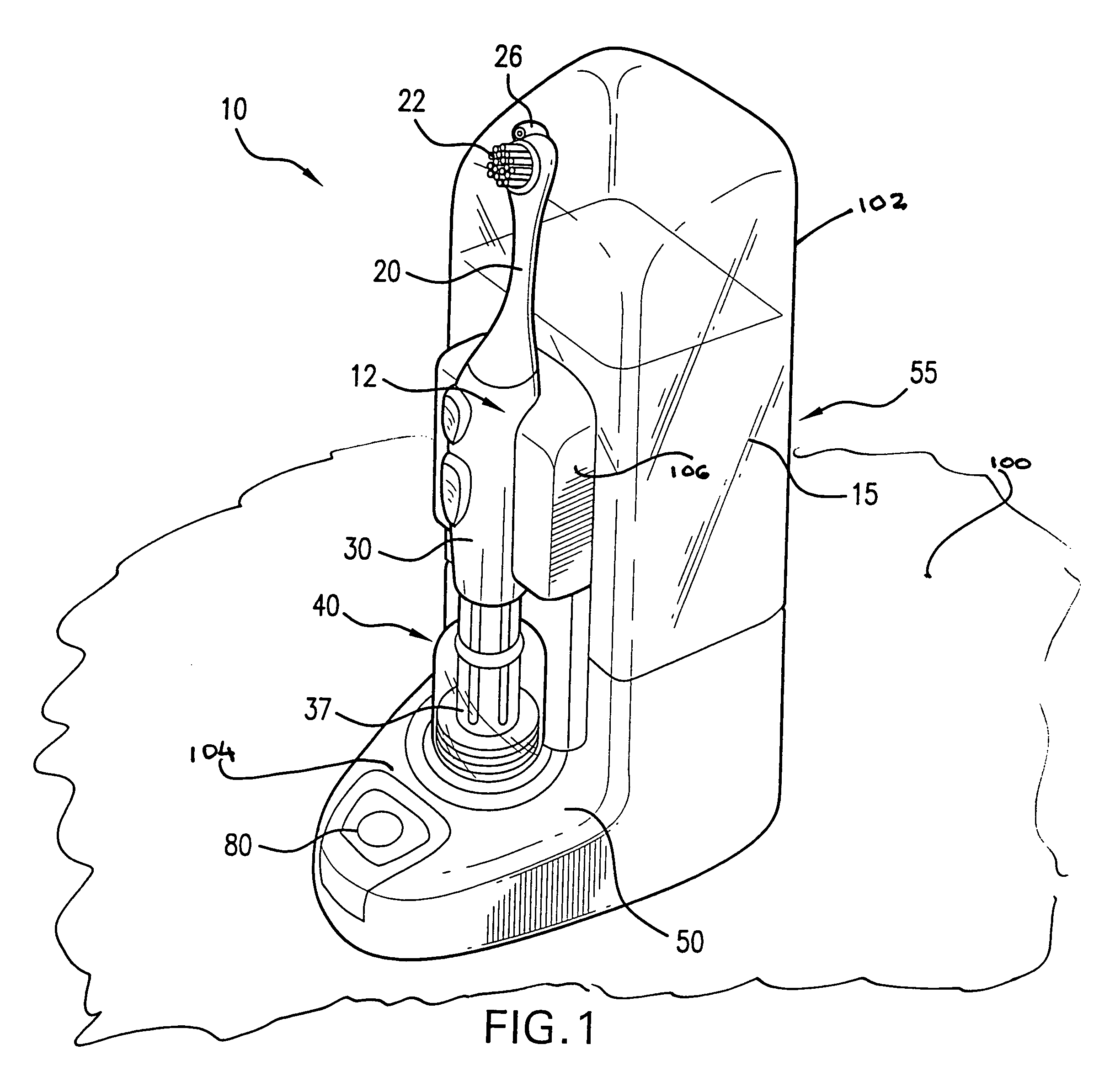
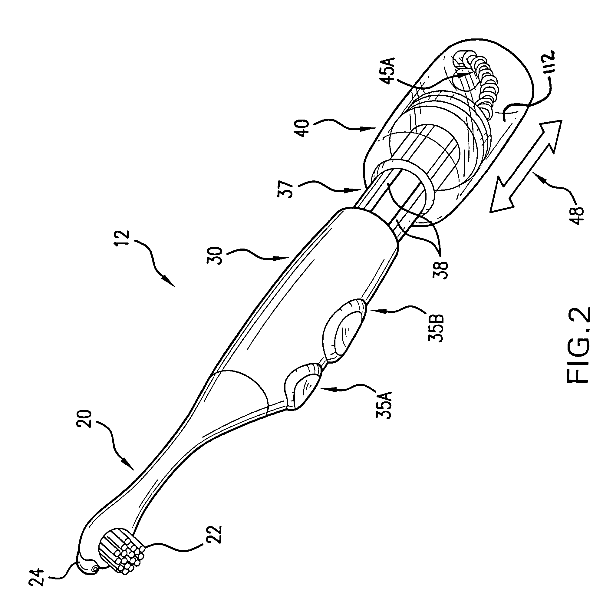
[0061]Referring now to FIGS. 1–8 and particularly with respect to FIGS. 1 and 8, there is shown dental hygiene device 10 which is adapted to be mounted on base surface 100. In dental hygiene device 10 includes docking base member 50 in combination with fluid reservoir housing 55 as shown. The combination of docking base member 50 and fluid reservoir housing 55 is substantially L-shaped in contour for permitting mounting of dental hygiene head 20, handle housing 30 and telescoping handle chamber housing 40 in combination within a base portion of docking base member 50 all combined in a compact and volume efficient manner. As is seen, fluid reservoir housing 55 contains fluid 15 which may be an antiseptic, antibacterial, fluoride, tartar control, whitening agent, or other prescription or over-the-counter fluid based medication, not important to the invention concept with the exception that fluid 15 be adapted to be emitted or passed through dental hygiene device 10 adjacent or through...


PUM


Abstract

A dental hygiene system provided with interchangeable dental heads permits power-enhanced brushing and concurrent fluid irrigation to optimize a user's personal dental hygiene efforts. The system has a handle assembly with an irrigation nozzle in close proximity to displaceable bristles driven by a battery-operated handle motor. Pumping of irrigation fluid such as an antiseptic solution into the oral cavity is also motor driven. A telescoping chamber with irrigation fluid fits on the piston-like base end of the handle and is refilled by docking the handle assembly on a complementary docking station that includes a detachable fluid reservoir, microswitch controls and a base fluid pump. Docking of the handle assembly triggers the microswitches and opens a check valve in the bottom of the handle chamber, which activates the flow of fluid from the reservoir into the chamber. An optional fiberoptic subassembly illuminates the oral cavity.

Description

RELATED PATENT APPLICATION[0001]The present patent application is based on U.S. Provisional Patent Application No. 60 / 484,291, filed on 3 Jul. 2003.FIELD OF THE INVENTION[0002]The field of this invention is dental hygiene devices. In particular this invention relates to dental hygiene devices in the form of powered toothbrushes. Still further this invention is directed to the field of dental hygiene devices where an antiseptic liquid is introduced into the oral cavity during a tooth brushing procedure.BACKGROUND OF THE INVENTION[0003]The present invention relates to a dental hygiene device, and more specifically an electrically power operated toothbrush system which may be battery operated which permits brushing of teeth and also irrigation of the periodontal and dental areas with an antiseptic solution or the like. In particular, the invention is directed to a toothbrush system a mechanism which irrigates periodontal structures and teeth with a fluid such as an antiseptic solution ...

Claims


Application Information

Patent Timeline
Patent Type & Authority Patents(United States)
IPC IPC(8): A61C17/02A46B13/04A61C1/08A61C17/22A61C17/28A61C17/36A61C19/06
CPCA61C17/222A61C17/28A61C17/36A61C17/225A61C1/088A61C17/0205A61C19/063
Inventor KLUPT, MICHAEL
Owner KLUPT MICHAEL
Why Eureka
Try Eureka