Heat-assisted magnetic recording head constituted of slider and light source unit, and manufacturing method of the head

a technology of magnetic recording head and slider, which is applied in special recording techniques, instruments, and record information storage, etc., can solve the problems of degrading the magnetic stability of the record bit, the head cannot write data to the magnetic recording medium, and the alignment between the light source unit and the slider is difficult to accurately recognize the location of the light-emission center. , to achieve the effect of high accuracy of alignmen

Active Publication Date: 2010-04-08
TDK CORPARATION
View PDF0 Cites 23 Cited by
  • Summary
  • Abstract
  • Description
  • Claims
  • Application Information

AI Technical Summary

Benefits of technology

[0036]In the manufacturing method according to the present invention, at least one displacement measuring means is preferably used to determine relative positions of the light source unit and the slider in a direction perpendicular to the element-integration surface. In the case, the at least one displacement measuring means is preferably at least one laser displacement meter; the at least one laser displacement meter is preferably used to apply laser light to the end surface of the head par...

Problems solved by technology

However, a problem is likely to occur that the decrease in size causes thermal stability of the magnetization of the record bit to be degraded.
Therefore, the head cannot write data to the magnetic recording medium when the coercive force of the medium exceeds the write field limit.
Accordingly, in both cases where the n-electrode is adhered and the p-electrode is exposed as the outer surface and where the p-electrode is adhered and the...

Method used


Image

  • Heat-assisted magnetic recording head constituted of slider and light source unit, and manufacturing method of the head
  • Heat-assisted magnetic recording head constituted of slider and light source unit, and manufacturing method of the head
  • Heat-assisted magnetic recording head constituted of slider and light source unit, and manufacturing method of the head

Examples


Embodiment Construction

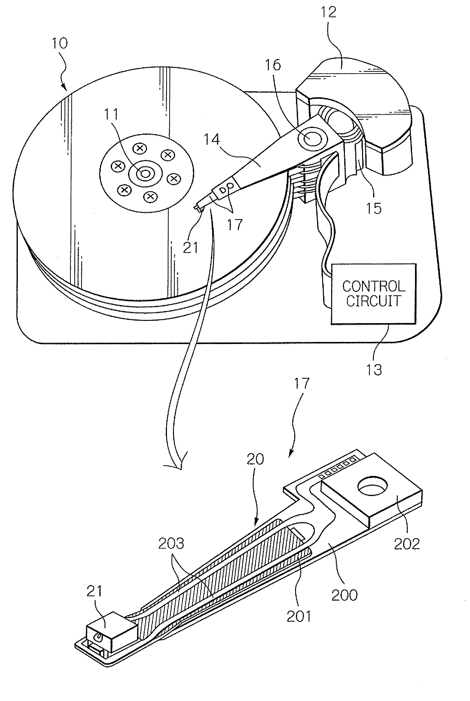
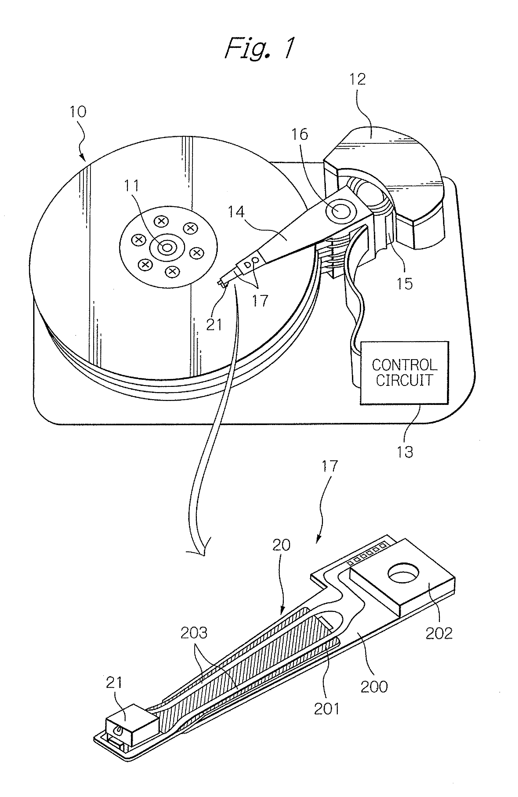
[0064]FIG. 1 shows a perspective view schematically illustrating a structure of a major part in one embodiment of a magnetic recording apparatus and a head gimbal assembly (HGA) according to the present invention. Here, in the perspective view of the HGA, the side of the HGA opposed to the surface of the magnetic disk is presented as the upper side.

[0065]A magnetic disk apparatus as a magnetic recording apparatus shown in FIG. 1 includes: a plurality of magnetic disks 10 rotating around a rotational axis of a spindle motor 11; an assembly carriage device 12 provided with a plurality of drive arms 14 thereon; an HGA 17 attached on the top end portion of each drive arm 14 and provided with a heat-assisted magnetic recording head 21; and a recording / reproducing and light-emission control circuit 13 for controlling write / read operations of the heat-assisted magnetic recording head 21 and further for controlling the emission operation of a laser diode as a light source that generates las...


PUM


Abstract

Provided is a method for manufacturing a heat-assisted magnetic recording head, capable of joining a light source unit and a slider with a sufficiently high alignment accuracy. In the method, the unit including a light source is joined to the slider including a head part. First, at least one marker provided on the head-part end surface is set so that the distance from the waveguide incident center to the marker end is substantially equal to the distance from the light-emission center of the light source to the end surface of the light source. After that, the unit and slider are relatively moved while keeping the unit in surface contact with the slider, and the relative positions are set so that the end of the marker coincides with, or is at a distance within an acceptable range from, the edge of the surface of the light source.

Description

BACKGROUND OF THE INVENTION[0001]1. Field of the Invention[0002]The present invention relates to a magnetic head including a light source, for writing signals by using heat-assisted magnetic recording, and to a method for manufacturing the magnetic head.[0003]2. Description of the Related Art[0004]As the recording density of a magnetic recording and reproducing apparatus, represented by a magnetic disk apparatus, becomes higher, further improvement has been required in the performance of a thin-film magnetic head. As the thin-film magnetic head, a composite-type thin-film magnetic head is widely used, which has a stacked structure of a magnetoresistive (MR) element for reading data and an electromagnetic transducer for writing data.[0005]A magnetic recording medium, on the other hand, generally is magnetically discontinuous, in which magnetic microparticles are gathered together. Usually, each of the magnetic microparticles has a single magnetic-domain structure, and in the medium, ...

Claims


Application Information

Patent Timeline
IPC IPC(8): G11B11/03G11B33/00
CPCG11B5/102G11B5/314G11B5/3163G11B5/4866Y10T29/49027G11B11/10536G11B11/1058G11B2005/0005G11B2005/0021G11B7/1387
Inventor SHIMAZAWA, KOJIITO, YASUHIRO
Owner TDK CORPARATION
Why Eureka
Try Eureka