
Paintball Work Table

Inactive Publication Date: 2010-04-15
MEDINA RODRIGO
View PDF21 Cites 7 Cited by
  • Summary
  • Abstract
  • Description
  • Claims
  • Application Information

AI Technical Summary

Benefits of technology

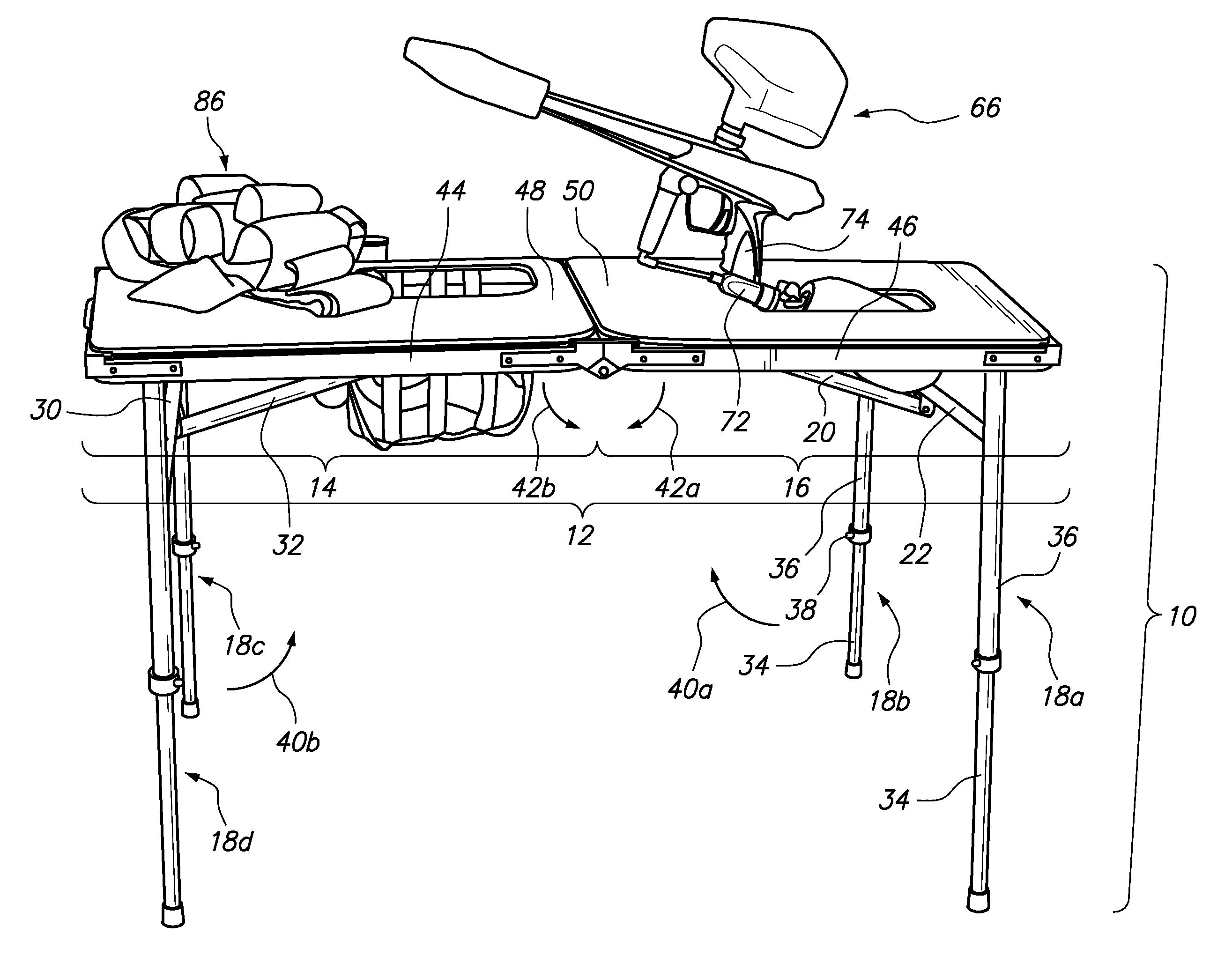
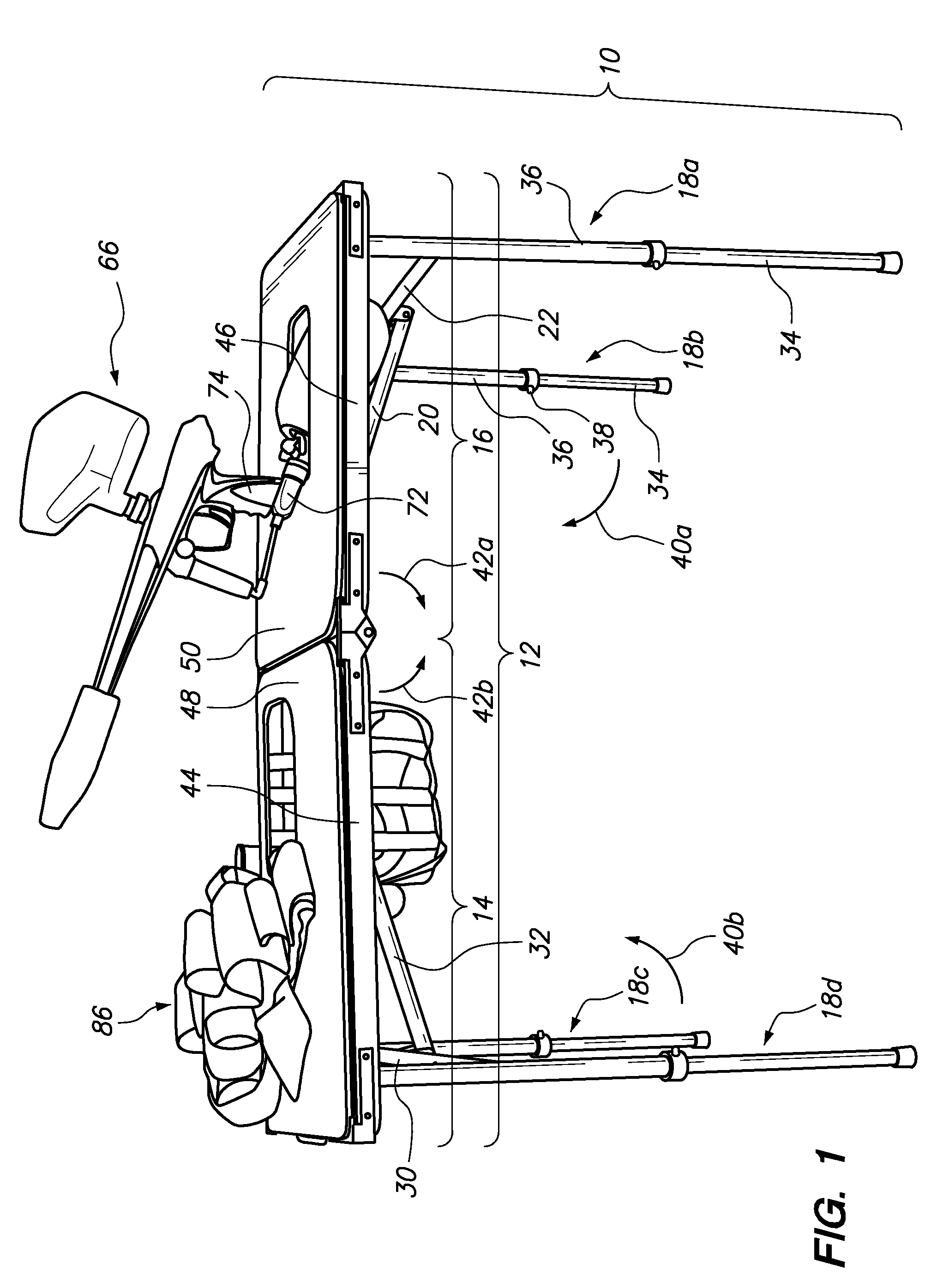
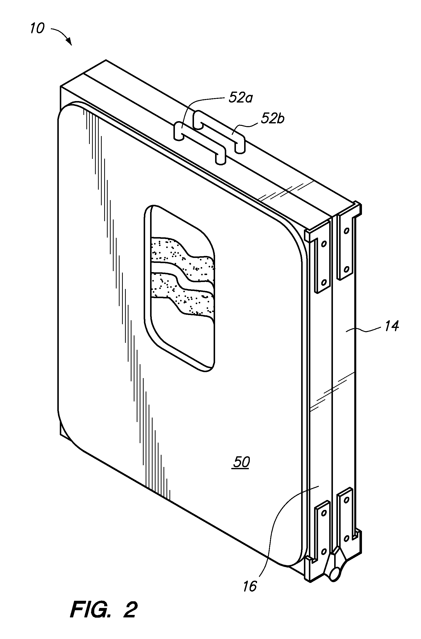
[0008]The paintball work table discussed herein addresses the needs discussed above, discussed below, and those that are known in the art. The paintball work table may be traversed between a folded position and an unfolded position. In the folded position, the paintball player may carry the paintball work table with a handle. In the unfolded position, the paintball work table provides an area for the paintball player to lay his/her paintball

Problems solved by technology

Unfortunately, the paintball player must lay his/her equipment on the ground or the back of a truck bed

Method used


Image

  • Paintball Work Table
  • Paintball Work Table
  • Paintball Work Table

Examples


Embodiment Construction

[0020]Referring now to FIG. 1, a paintball work table 10 in an unfolded position is shown. The paintball work table 10 may have a tabletop 12 comprised of two halves 14, 16. The paintball work table 10 may additionally have four legs 18a, b, c, d. The legs 18a, b may be pivotably attached to the second half 16 of the tabletop 12 at its distal end portion. The legs 18c, d may be pivotably attached to the first half 14 of the tabletop 12 at its distal end portion. The legs 18a, b, c and d are traversable to the unfolded position with a telescoping brace 20 (see FIG. 3) and a cross member 22 (see FIG. 3). The cross member 22 may be rigidly secured to the legs 18a, b at its upper portion. The telescoping brace 20 may be pivotably attached to the middle section of the cross member 22 and the underside of the second half 16 of the tabletop 12. The telescoping brace 20, as shown in FIG. 3, may have a first tube 24 slidably disposable within a second tube 26. The first tube 24 may be slid i...


PUM


Abstract

A paintball work table having a paintball pod carry suspender, helmet cavity and paintball gun cavity is described herein. The paintball work table permits the paintball player to effectively and efficiently manage his/her equipment between paintball scrimmages. Also, the paintball work table may be foldable and easy to carry.

Description

CROSS-REFERENCE TO RELATED APPLICATIONS[0001]Not ApplicableSTATEMENT RE: FEDERALLY SPONSORED RESEARCH / DEVELOPMENT[0002]Not ApplicableBACKGROUND[0003]The present invention relates to a work table for preparing and / or storing paintball equipment including a paintball gun, paintball helmets and paintball pods.[0004]Paintball players invest hundreds and thousands of dollars in their paintball equipment. By way of example and not limitation, a quality paintball gun may cost approximately one thousand to fifteen hundred dollars ($1,000-$1,500). Accordingly, paintball players take care of their equipment such that their equipment is not scratched, dinged, etc.[0005]During paintball play, a paintball player may play a number of paintball scrimmages during the day. Between each paintball scrimmage, the paintball player may perform maintenance on his / her paintball gun and also reload the paintball pods with paintballs.[0006]Unfortunately, the paintball player must lay his / her equipment on the...

Claims


Application Information

Patent Timeline
IPC IPC(8): A47B3/00A47B37/00A47B13/08
CPCA47B3/0913A47B37/00A47B13/16
Inventor MEDINA, RODRIGO
Owner MEDINA RODRIGO
Learn More