Method and apparatus for improving distribution of fluid in a heat exchanger

a heat exchanger and fluid distribution technology, applied in indirect heat exchangers, lighting and heating apparatus, refrigeration components, etc., can solve problems such as significant reduction in heat exchanger efficiency and two-phase maldistribution, and achieve the effect of reducing the internal volume of a manifold and reducing the maldistribution of fluid

Inactive Publication Date: 2010-04-15
DELPHI TECH INC +1
View PDF7 Cites 75 Cited by
  • Summary
  • Abstract
  • Description
  • Claims
  • Application Information

AI Technical Summary

Benefits of technology

This patent describes how to improve the distribution of fluids in small heat exchangers by reducing the amount of space available for them. By doing this, it helps ensure that all parts of the system are getting enough attention from the fluid, which can lead to better performance overall.

Problems solved by technology

The technical problem addressed in this patent text is the non-uniform distribution of two-phase fluid in parallel mini-channel tubes, which results in reduced heat exchanger efficiency due to maldistribution. There is a need for a method and apparatus to increase uniformity in the distribution of the two-phase fluid mixture in these heat exchangers.

Method used


Image

  • Method and apparatus for improving distribution of fluid in a heat exchanger
  • Method and apparatus for improving distribution of fluid in a heat exchanger
  • Method and apparatus for improving distribution of fluid in a heat exchanger

Examples


Embodiment Construction

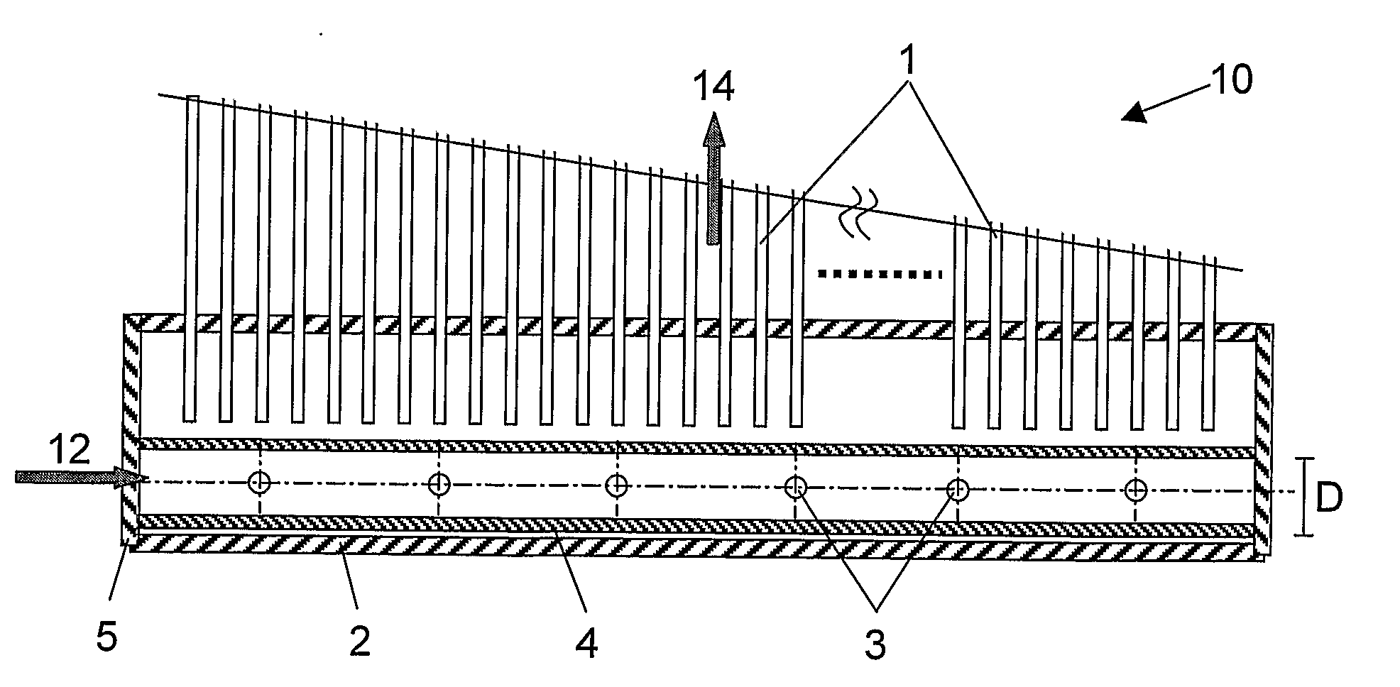
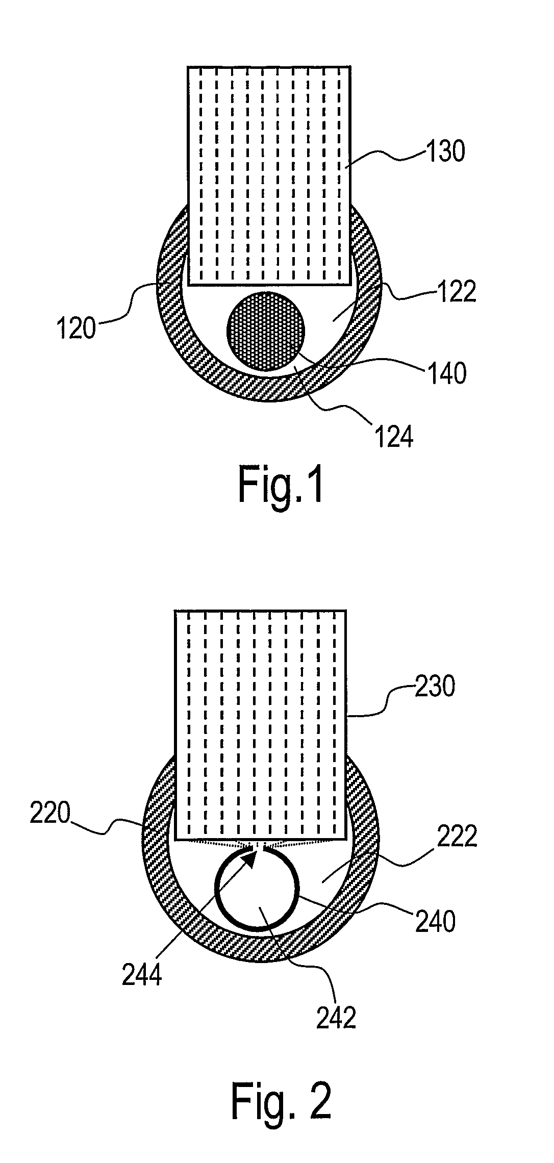
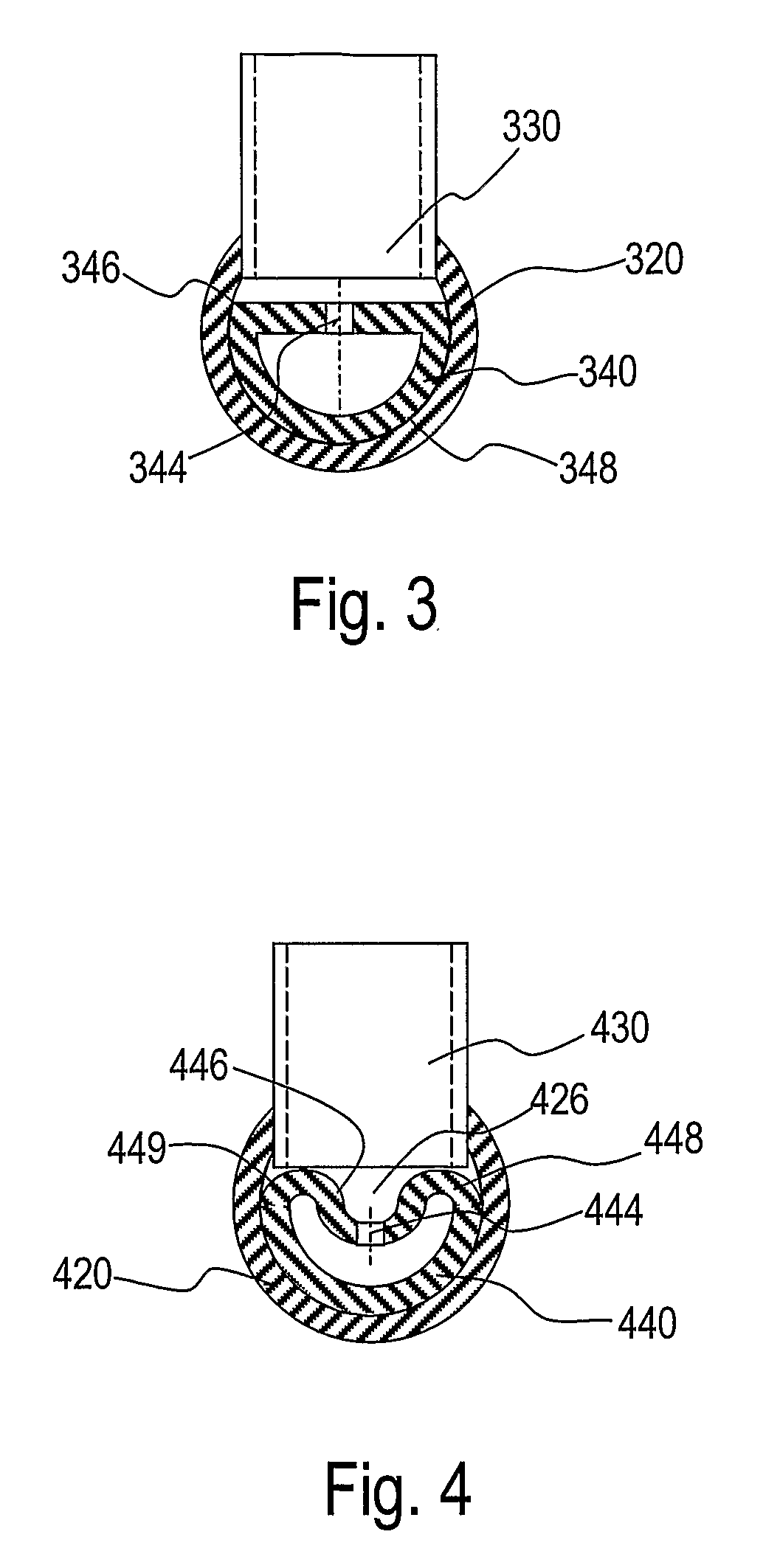
[0023]It has been determined by the present disclosure that maldistribution in a MCHX heat exchanger, e.g., evaporator, condenser, gas cooler, or any other heat exchanger, may be reduced by reducing an internal volume of a manifold or header that distributes a multiple-phase flow, for example, a two-phase flow including both a vapor and a liquid, to parallel refrigerant paths, for example, tubes. Without wishing to be bound by any particular theory, it is believed that by reducing the total internal volume of the manifold, the velocity and mass flux of a two-phase fluid can be increased promoting internal mixing and also a volume over which a gas phase and a liquid phase of the two-phase flow separates is reduced as a result of these factors a relatively uniform and homogeneous mixture of vapor and liquid can be distributed to tubes that are parallel. Advantageously, it has been determined that an insert or shape of the manifold reduces the internal volume of the manifold. The inser...


PUM


Abstract

A mini-channel heat exchanger or a micro-channel heat exchanger includes an insert (140, 240, 340, 440, 540, 640, 4, 940, 1040) having a volume. The insert is within a gap between a plurality of tubes (130, 230, 330, 430, 530, 630, 1, 930, 1030) of the mini-channel heat exchanger or the micro-channel heat exchanger and a manifold inner wall of a manifold (120, 220, 320, 420, 520, 620, 2, 920, 1020).

Description


Claims


Application Information

Patent Timeline
Owner DELPHI TECH INC
Why Eureka
Try Eureka