System and method for uniformly distributing a fluid through a filter bed in a filter

a filter bed and fluid technology, applied in the field of filter systems, can solve problems such as maldistribution of washing fluid or influent, and achieve the effect of reducing or eliminating maldistribution and reducing fluid maldistribution

Active Publication Date: 2011-09-22
ROBERT MARKETING DE
View PDF3 Cites 4 Cited by
  • Summary
  • Abstract
  • Description
  • Claims
  • Application Information

AI Technical Summary

Benefits of technology

[0024]Still another embodiment of the present inventions, is directed to an apparatus for reducing maldistribution of a fluid through a filter bed in a filter system having an underdrain disposed below the filter bed and a fluid distribution chamber operably associated with the underdrain for directing a fluid through the underdrain. The apparatus includes a first distribution member operably associated with the underdrain through which one or more fluids pass in route to the filter bed. The first distribution member is adjustable so that one or more hydraulic characteristics of the first distribution member can be adjusted without replacing the first distribution member to compensate for pressure variances in the fluid distribution chamber to reduce or eliminate maldistribution.

Problems solved by technology

Therefore, these types of underdrains cannot compensate for pressure variances in the plenum resulting in maldistribution of the washing fluid or influent in those instances where the washing fluid and / or influent passes from the plenum through the underdrain prior to entering the filter bed.

Method used


Image

  • System and method for uniformly distributing a fluid through a filter bed in a filter
  • System and method for uniformly distributing a fluid through a filter bed in a filter
  • System and method for uniformly distributing a fluid through a filter bed in a filter

Examples


example a

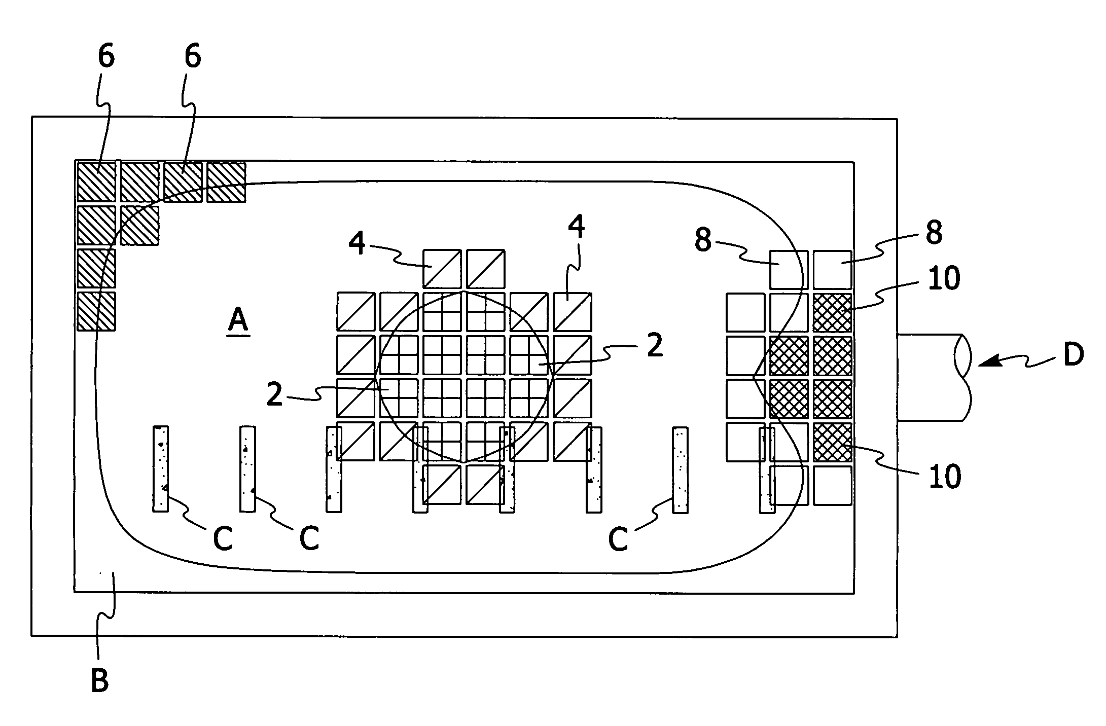
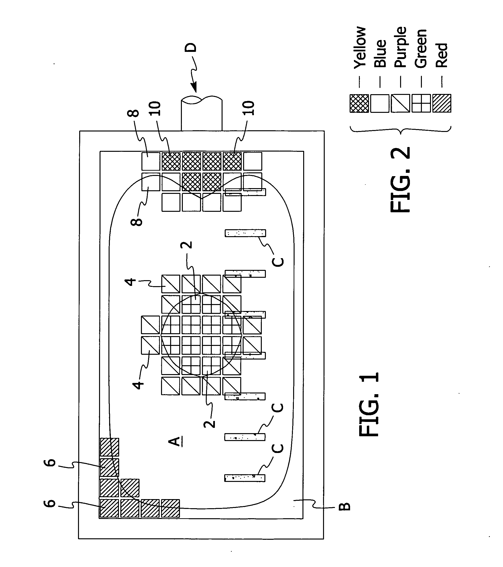
[0052]Assume the following conditions exist: (i) an existing filter with a monolithic Wheeler bottom underdrain system; (ii) a design backwash flow rate of 20 m / ft2 of filter area; (iii) plenum pressures at 20 gpm / ft2 have been measured at various locations across the filter varying from 3.6 ft at the lowest to 5.6 ft. at the highest; (iv) a control orifice diameter of 0.75 in.; and, (v) the discharge coefficient of the control orifice is 0.95.

[0053]Flow thru an orifice can be determined by the following well known equation:

Q=19.636Cd√{square root over (h)}

Where Q=flow thru the orifice in gpm, C=the orifice discharge coefficient (dimensionless), d=the diameter of the orifice in inches and h=the headloss across the orifice in ft. water column This equation may be rearranged to solve for the orifice diameter d, as follows:

d=[Q19.636Ch]1 / 2

Knowing the desired flow rate through each of the orifices (in most cases it will be desired to have substantially the same flow rate through each of...


PUM

PropertyMeasurementUnit
sizeaaaaaaaaaa
pressureaaaaaaaaaa
shapeaaaaaaaaaa

Abstract

A system and method for uniformly distributing fluids (e.g., washing and in-service) through a filter bed of a filter. The system and method of the present invention can be used with any type of filter that uses media to remove impurities from a fluid. The filter bed can include one or more layers of media. The media can be natural (e.g., sand, gravel, anthracite, etc.) or can be fabricated (e.g., plastic). The filter media can be supported by one or more layers of gravel. Alternatively, the filter media can be supported by a porous plate or other support designed to replace the gravel layers. The present invention includes a system having one or more distribution members configured to uniformly distribute a fluid through a filter bed of a filter. Preferably, the one or more distribution members can be readily installed by relatively unskilled labor in both existing filters and new filters. In a preferred embodiment, the one or more distribution members are configured to extend into at least a portion of an underdrain from above the underdrain. In retrofit applications, the preferred design of the one or more distribution members is such that no significant alteration of the distribution chamber, underdrain or fluid velocity is necessary.

Description

RELATED APPLICATIONS[0001]The subject patent application is a continuation-in-part of U.S. patent application Ser. No. 11 / 606,012 filed on Nov. 30, 2006, the entire contents of which are incorporated herein by reference, which is a continuation-in-part of U.S. patent application Ser. No. 11 / 588,210 filed on Oct. 27, 2006, the entire contents of which are incorporated herein by reference.FIELD OF THE INVENTION[0002]The present invention is directed to a filter system in which one or more fluids pass through a filter bed at various times (e.g., a washing mode and / or a filtration mode). More specifically, the present invention is directed to a system and method for uniformly distributing one or more fluids (e.g., washing and / or in-service) through a filter bed in a filter. The fluids may include a liquid, a gas or a combination of a liquid and a gas. Where a combination of a liquid and gas is used, the liquid and gas can be directed through the filter bed simultaneously or separately. ...

Claims


Application Information

Patent Timeline
Patent Type & Authority Applications(United States)
IPC IPC(8): B01D24/00B01D24/38B01D24/46B23P11/00
CPCB01D24/24B01D24/4631Y10T137/0402
Inventor ROBERTS, R. LEEADDISON, MARK KEVIN
Owner ROBERT MARKETING DE
Why Eureka
Try Eureka