Surgical instrument for tensioning plate-shaped engaging elements with respect to each other

a technology of engaging elements and surgical instruments, applied in the field of surgical instruments, can solve problems such as unfavorable uneven tension distribution

Inactive Publication Date: 2010-04-15
AESCULAP AG
View PDF1 Cites 17 Cited by
  • Summary
  • Abstract
  • Description
  • Claims
  • Application Information

AI Technical Summary

Benefits of technology

[0008]In accordance with a preferred embodiment, it may be provided that the compensating element is configured as a carrying arm on which the grip elements are held at a spacing from each other, and on which the tensioning device engages between the holding points of the grip elements in such a way that the carrying arm is pivotable relative to the tensioning direction of the tensioning device.
[0009]In particular, it may be provided that the grip elements are held at their holding point on the carrying arm in such a way that the carrying arm is pivotable relative to the grip elements. In a manner similar to the arm of a balance, it is therefore possible for the carrying arm to transmit the displacement movement imparted to it by the tensioning device to a different extent onto the two grip elements. When the carrying arm is pivoted, the grip elements are displaced to a greater extent on one side than the carrying arm itself, and to a lesser extent on the opposite side.

Problems solved by technology

The two plate-shaped engaging elements are thereby inevitably displaced parallel to each other when the tensioning device is actuated, so that the engaging elements are unable to follow a structure of the bone plates accommodated between them, which is not exactly parallel.
This results in different values of the contact pressure of the engaging elements on the bone portions lying between them and, consequently, in different tensions.
Such an uneven distribution of tensions may prove unfavorable.

Method used


Image

  • Surgical instrument for tensioning plate-shaped engaging elements with respect to each other
  • Surgical instrument for tensioning plate-shaped engaging elements with respect to each other
  • Surgical instrument for tensioning plate-shaped engaging elements with respect to each other

Examples


Embodiment Construction

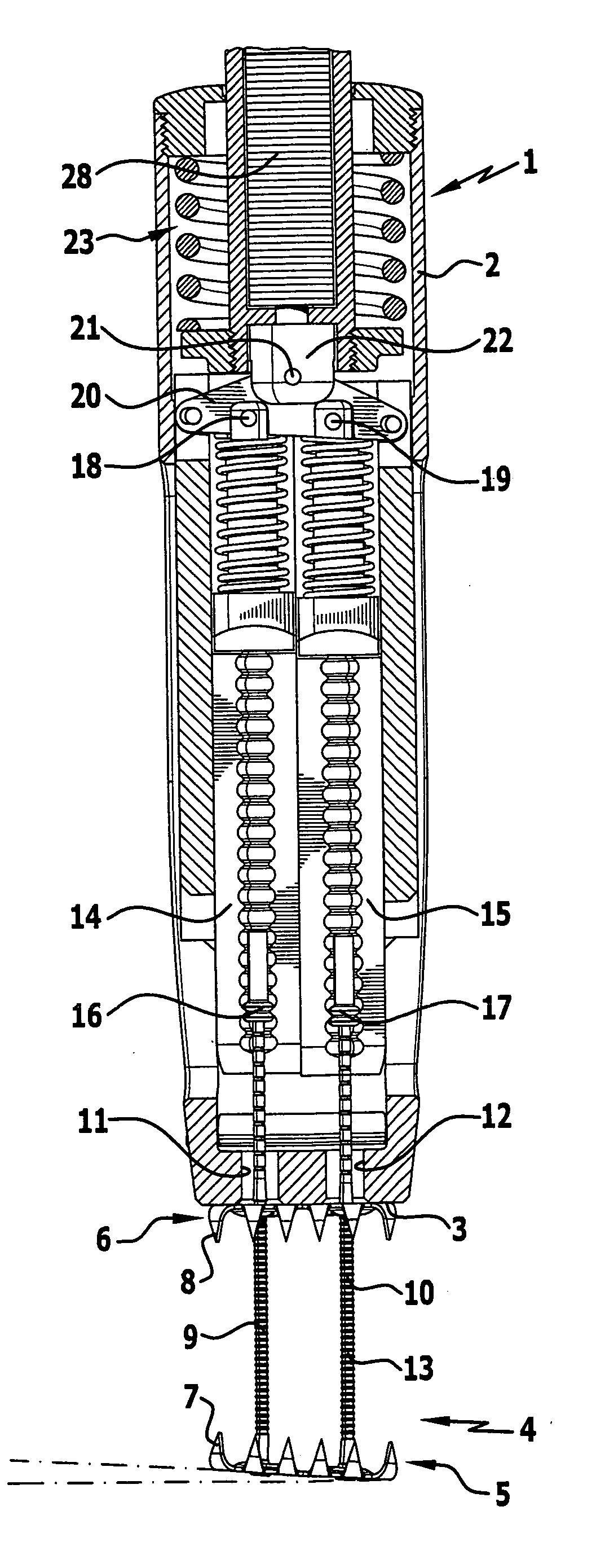
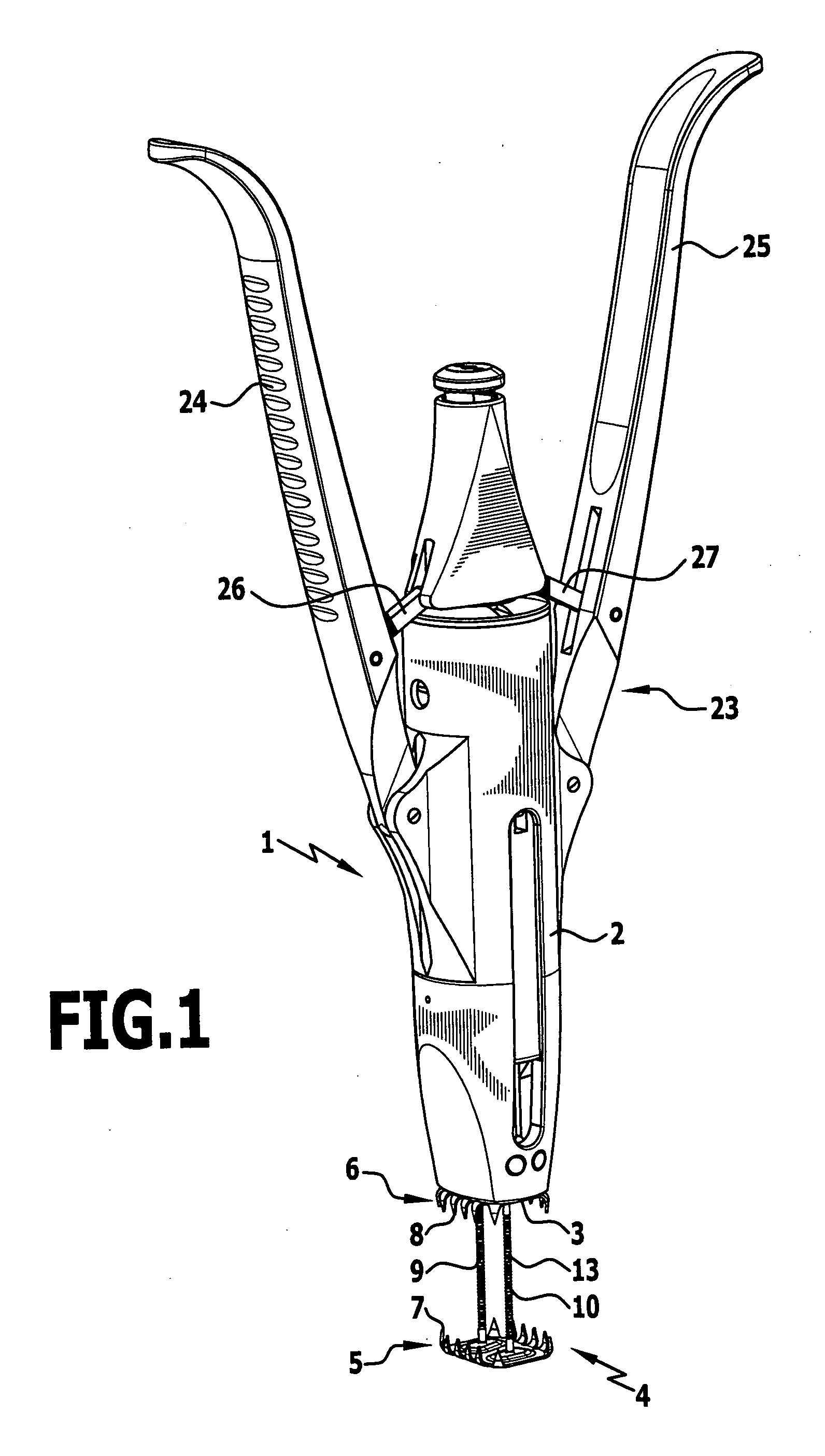
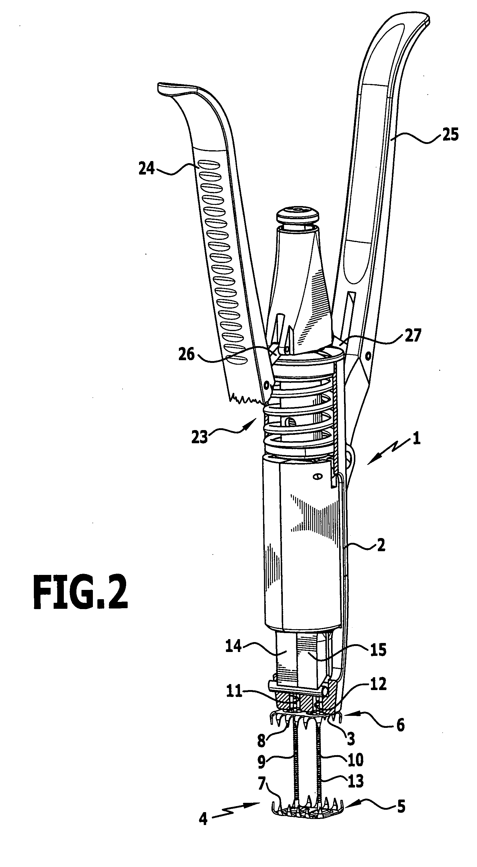
[0016]The instrument 1 shown in the drawings is very similar in construction to the instrument described in DE 103 10 004 B3. Therefore, reference is made explicitly to the corresponding description of this previously published document. DE 103 10 004 B3 is incorporated herein and made a part hereof by reference.

[0017]This instrument 1 has a substantially cylindrical housing 2, at the bottom, distal end of which an engaging surface 3 is formed, with which the instrument 1 can be applied to an implant 4.

[0018]This implant comprises a first, lower engaging plate 5 and a second, upper engaging plate 6, which are both provided at their edge with pointed teeth 7, 8 which project from the plane of the engaging plates and point in the direction of the respective other engaging plate. The first engaging plate carries two quite long pin-shaped connecting members 9, 10 extending parallel and next to each other. The connecting members 9, 10 pass through corresponding openings in the second eng...


PUM


Abstract

In a surgical instrument for tensioning two plate-shaped engaging elements with respect to each other at opposite sides of bone portions, a first engaging element carrying next to each other at a spacing from each other two pin-shaped or rod-shaped connecting members which pass through openings in the second engaging element, with a supporting surface for engagement on the side of the second engaging element that faces away from the first engaging element, and with a tensioning device engaging the connecting members for displacement of the connecting members and consequently of the first engaging element in the direction towards the second engaging element, to enable an individual adjustment of the engaging elements to the shape of the bone portions, it is proposed that the surgical instrument comprise next to each other two grip elements, each releasably connectable to a connecting member, and that the tensioning device engage the grip elements through a compensating element which, upon tensioning of the tensioning device, allows a differently sized displacement of the two grip elements and consequently of the two connecting members.

Description

[0001]This application is a continuation of international application number PCT / EP2008 / 004129 filed on May 23, 2008.[0002]The present disclosure relates to the subject matter disclosed in international application number PCT / EP2008 / 004129 of May 23, 2008 and German application number 10 2007 026 079.4 of May 25, 2007, which are incorporated herein by reference in their entirety and for all purposes.BACKGROUND OF THE INVENTION[0003]The invention relates to a surgical instrument for tensioning two plate-shaped engaging elements with respect to each other at opposite sides of bone portions, a first engaging element carrying next to each other at a spacing from each other two pin-shaped or rod-shaped connecting members which pass through openings in the second engaging element, with a supporting surface for engagement on the side of the second engaging element that faces away from the first engaging element, and with a tensioning device engaging the connecting members for displacement ...

Claims


Application Information

Patent Timeline
Patent Type & Authority Applications(United States)
IPC IPC(8): A61B17/58
CPCA61B17/688A61B17/8869A61B17/823
Inventor LUTZE, THEODORDWORSCHAK, MANFREDMORALES, PEDROWEISSHAUPT, DIETER
Owner AESCULAP AG
Why Eureka
Try Eureka