Overlay Display Device

a display device and overlay technology, applied in the field of overlay displays, can solve the problems of not being able to install an mfd in the small confines of a typical cockpit, and not being able to design a solution well

Inactive Publication Date: 2010-04-22
RAYTHEON CO
View PDF3 Cites 35 Cited by
  • Summary
  • Abstract
  • Description
  • Claims
  • Application Information

AI Technical Summary

Benefits of technology

[0018]Some embodiments of the disclosure may provide one or more technical advantages. For example, in one embodiment, an overlay display device or system may be operable to access information from multiple sources or instruments on a single MFD that would otherwise be provided by multiple displays from multiple instruments while in the image-viewing mode and provide access to information from other instruments, instrument panels and / or displays over which the display device may be placed while in the see-through mode.

Problems solved by technology

However, it is often the case that all or most instruments must be retained, hence, there is no location for installing an MFD in the small confines of a typical cockpit.
However, this is not a well designed solution.
Further, some of the instruments may have data that may not be compatible for display on an MFD and may therefore require their own display units.

Method used


Image

  • Overlay Display Device
  • Overlay Display Device
  • Overlay Display Device

Examples


Embodiment Construction

[0026]Preferred embodiments of the disclosure and its advantages may be best understood by reference to FIGS. 1-4.

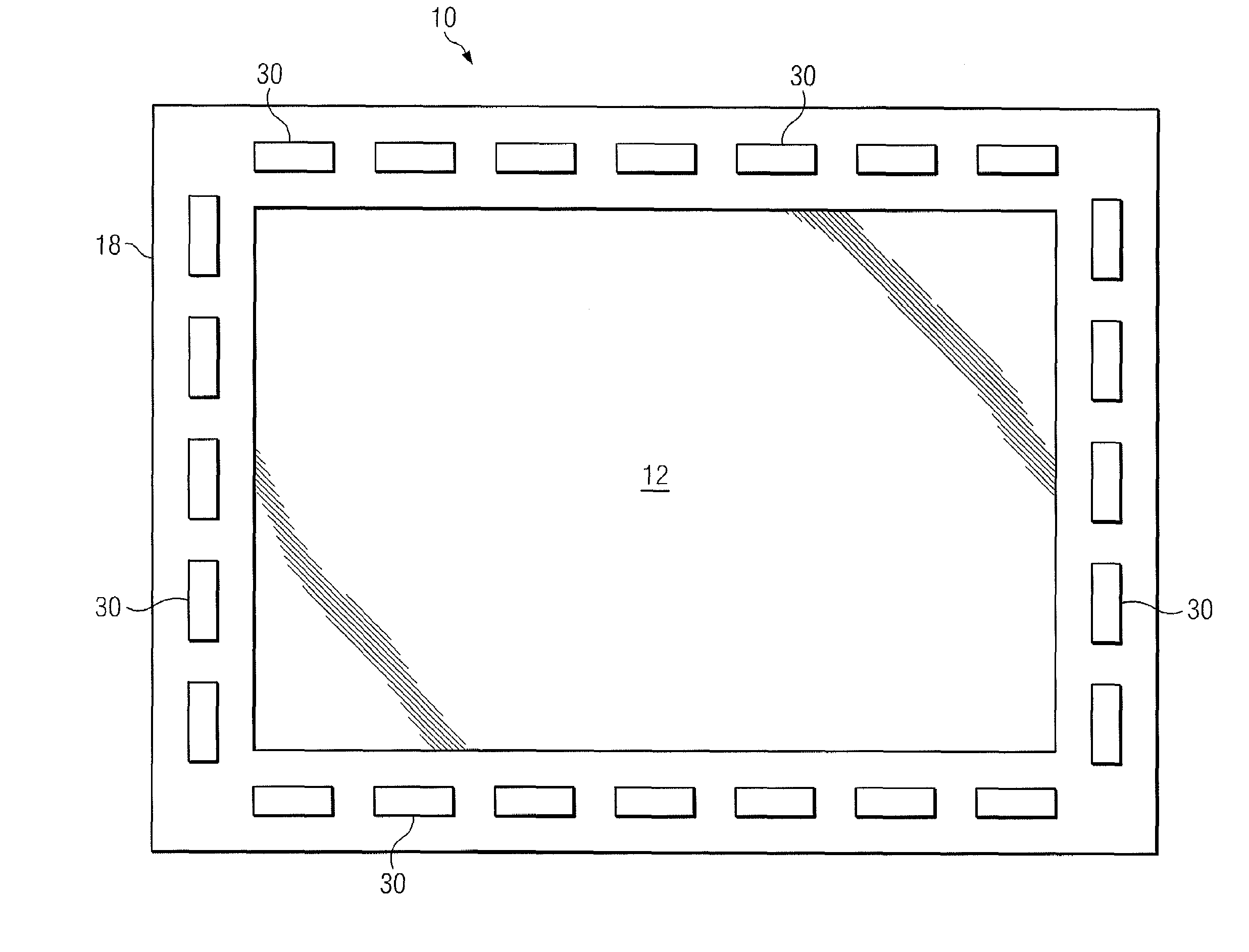
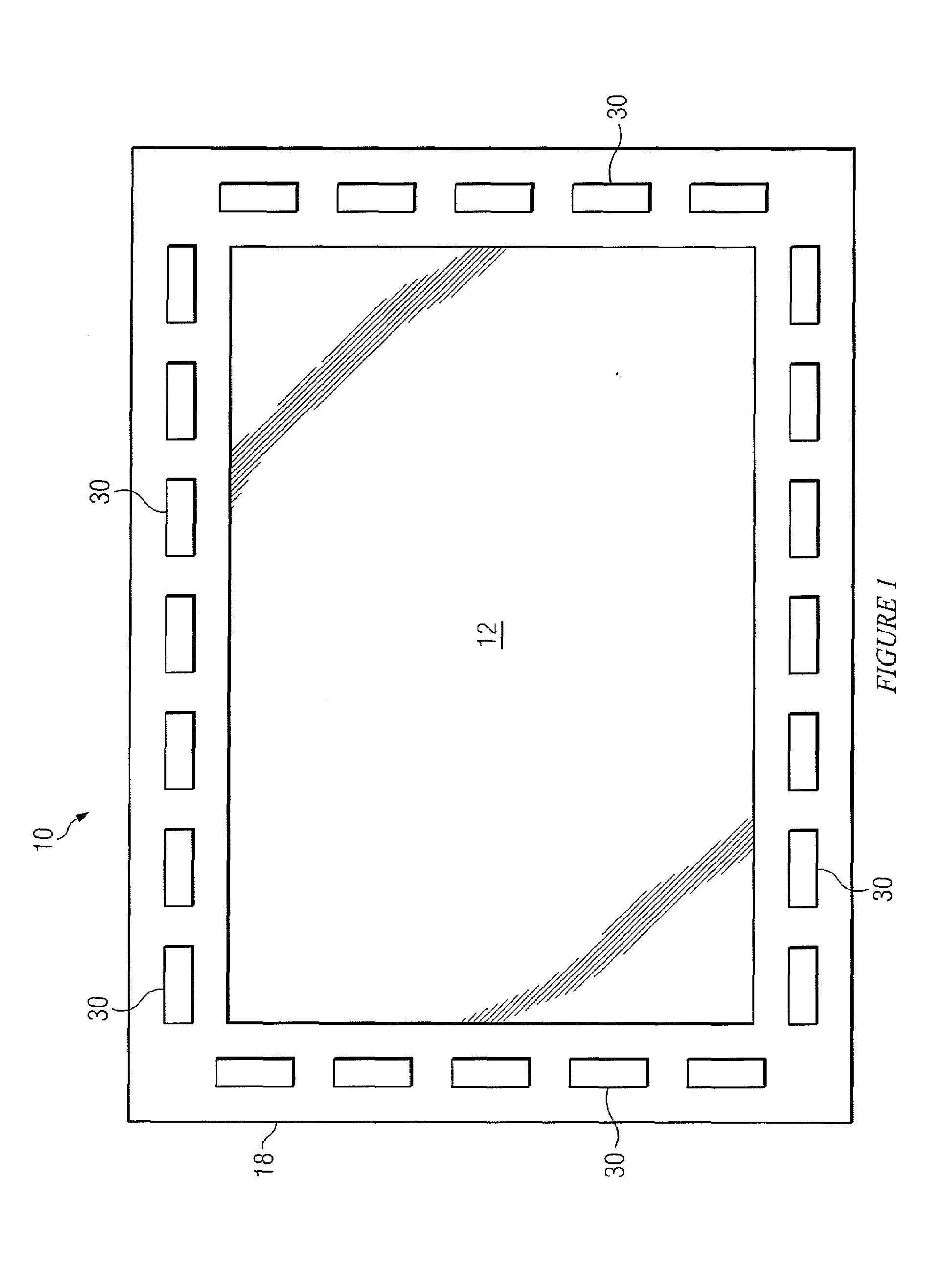
[0027]FIG. 1 depicts a frontal view of an example display device 10 and may include a display screen or display glass 12 encased in a display bezel 18. In some embodiments, display device 10 may be an overlay display device configured to be disposed on a surface (e.g., a surface of other instruments, instrument panels or display units) (depicted later in FIGS. 3 and 4).

[0028]In some embodiments, display bezel 18 may also include one or more buttons 30 operable to manipulate various devices and / or controls (e.g., electronic controls) comprised in display device 10. In other embodiments, controls operating and / or controlling components of display device 10 may be located separately for example in a separate control unit not located in a bezel (not expressly depicted).

[0029]Display screen 12 may be any suitable type of display glass material operable to display or form an i...


PUM


Abstract

The present disclosure relates to display devices and/or systems comprising a display screen configured to switch from a translucent image-display mode to a transparent see-through mode, configured adjacent a smart glass configured to switch from an opaque-mode to a transparent mode, with a cavity disposed in between. The cavity may be selectively illuminated by a light source. A display device/system may be enclosed in a bezel which may be configured to be mounted onto a surface such as an instrument panel or another display unit thereby providing an overlay display device. Electronic control units may selectively switch a display device from an image viewing-mode (i.e., display screen displays an image; smart glass is opaque; and light source is on), where the surface below is not visible to a see-through mode (i.e., display screen and smart glass are transparent; and light source is off), where the surface below is visible.

Description

CROSS-REFERENCE TO RELATED APPLICATIONS[0001]This application claims the benefit of U.S. Provisional Patent Application Ser. No. 61 / 106,054, filed Oct. 16, 2008, the contents of which are hereby incorporated in their entirety by reference.TECHNICAL FIELD OF THE DISCLOSURE[0002]The present disclosure relates, in some embodiments, to devices, systems, and / or methods relating to an overlay display. In some embodiments, an overlay display device and / or system of the disclosure may be placed over existing infrastructure (e.g., an instrument panel) and may be operable in a first mode to display images and may further be operable in a second mode to be transparent and provide visibility of the existing infrastructure over which the display device may be placed.BACKGROUND OF THE DISCLOSURE[0003]A typical airplane cockpit may be configured with instruments that provide information to a pilot and may include navigation instruments such as an altimeter, an airspeed indicator, a horizontal situ...

Claims


Application Information

Patent Timeline
Patent Type & Authority Applications(United States)
IPC IPC(8): G09G5/00
CPCB60K35/00G09G3/36G09G2300/023
Inventor MCMAHON, ROY P.
Owner RAYTHEON CO
Why Eureka
Try Eureka