Assymetrical progressive lens

a progressive lens and assymetric technology, applied in the field of assymetrical progressive lenses, can solve the problems of limiting the wearer's horizontal natural eye movement, primarily vertical or almost vertical power distribution,

Active Publication Date: 2010-04-22
SHAMIR OPTICAL IND LTD
View PDF3 Cites 34 Cited by
  • Summary
  • Abstract
  • Description
  • Claims
  • Application Information

AI Technical Summary

Problems solved by technology

However, the conventional design may result in primarily vertical or almost vertical power distribution.
As a result of the conventional design described above, the lens may limit the wearer's horizontal natural eyes movement and forces him to use his head to look at the sides.

Method used


Image

  • Assymetrical progressive lens
  • Assymetrical progressive lens
  • Assymetrical progressive lens

Examples


Embodiment Construction

[0015]In the following detailed description, numerous specific details are set forth in order to provide a thorough understanding of the invention. However, it will be understood by those skilled in the art that the present invention may be practiced without these specific details. In other instances, well-known methods, procedures, and components have not been described in detail so as not to obscure the present invention.

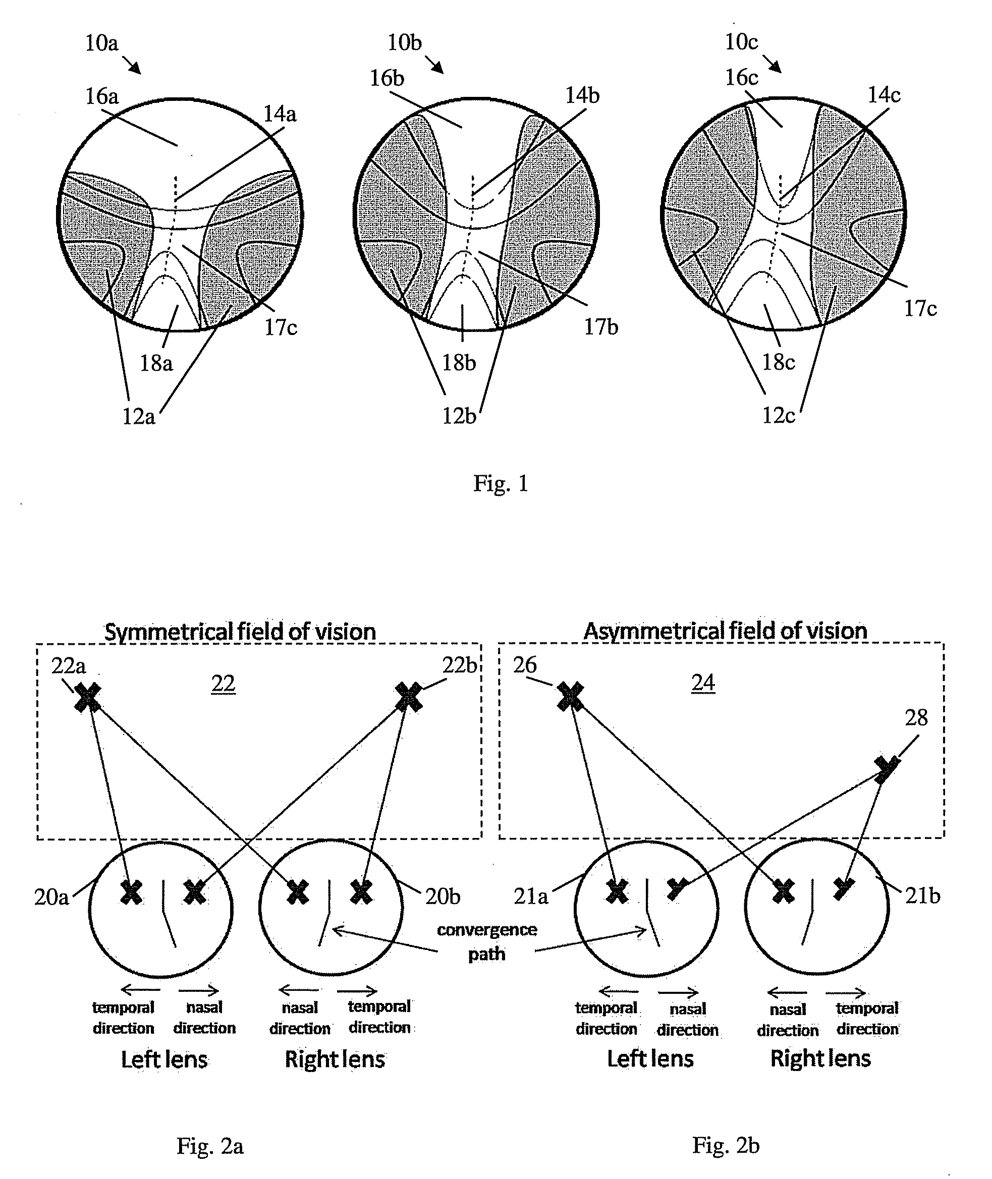
[0016]Reference is now made to FIG. 1, which is a schematic illustration of conventional right lens power distribution designs 10a, 10b and 10c. Power distribution designs 10a, 10b and 10c include respective far vision power zones 16a, 16b and 16c, intermediate vision power zones 17a, 17b and 17c, and near vision power zones 18a, 18b and 18c. Far vision power zones 16a, 16b and 16c may be located at the upper portion of power distribution designs 10a, 10b and 10c, for example, because users of lens tend to raise their gaze when looking at far distances. Near visio...


PUM


Abstract

Progressive lens for viewing a field of vision having at least a first portion including objects in a first range of distances from a viewer and a second portion including objects in a second range of distances from the viewer, the lens comprising: at least two different power zones, the first power zone having lens power required by the viewer for the first range of distances of viewed objects from the viewer, and the second power zone having lens power required by the viewer for the second range of distances of viewed objects from the viewer, wherein the size and location on the lens of the first power zone correspond to size and location in the field of vision of the first portion, and wherein the size and location on the lens of the second power zone correspond to size and location in said field of vision of the second portion.

Description

BACKGROUND OF THE INVENTION[0001]Progressive lenses are usually used by persons who need different lens power for different distances. Conventional progressive lenses usually designed in agreement with the fact that usually a wearer lowers his gaze in order to look at close distances. The design of conventional progressive lenses is usually based on two main assumptions: it is assumed that the main usage of the lens is along its vertical central meridian, with possible deviation to account for small eye convergence for near vision tasks, and it is assumed that the objects' distances distribution is symmetrical with respect to central vertical meridian of the visual field.[0002]These assumptions make it possible, and indeed that is what usually being done, to make the lens design for one eye (left or right) as the “mirror reflection” of the lens design for the other eye (for the same prescription) in terms of its power and astigmatism distributions across the lens.[0003]However, the ...

Claims


Application Information

Patent Timeline
Patent Type & Authority Applications(United States)
IPC IPC(8): G02C7/06
CPCG02C7/066G02C7/061
Inventor KATZMAN, DANWEINROT, GABBY
Owner SHAMIR OPTICAL IND LTD
Why Eureka
Try Eureka