
Method for manufacturing multifocal lenses

Inactive Publication Date: 2006-03-21
ESSILOR INT CIE GEN DOPTIQUE
View PDF17 Cites 24 Cited by
  • Summary
  • Abstract
  • Description
  • Claims
  • Application Information

AI Technical Summary

Benefits of technology

[0024]In all of the above-described deposition methods, deposition may be controlled by a feedback mechanism that enables deposition of a complex surface geometry conforming to a polynomial or sum of polynomials each describing a segment of the surface and smoothed over at the boundaries by means of splines or other fitting routines. Suitable feedback mechanisms include, without limitation, a reflectance measurement using a fiber optic light source and detector. Using a focused light source with a spot size of less than about 1 mm and preferably about 100 microns, the deposited layer thickness may be measured accurately as deposited. The information is fed back to the deposition system using a proportional integral derivative process controller. Alternatively, the actual focal length of the entire lens at a given position may be measured using a focused light source and detector, the light source spot size being less than about 1 mm. The focal length of the lens may be measured and compared to the desired focal length at various positions across the lens.

Problems solved by technology

However, an inherent disadvantage in PAL's is that, due to the incorporation of the power for the near vision zone, the lens' center thickness is increased in comparison to single vision lenses.
This makes the PAL less desirable from a cosmetic standpoint to the lens wearer.

Method used


Image

  • Method for manufacturing multifocal lenses
  • Method for manufacturing multifocal lenses

Examples


Embodiment Construction

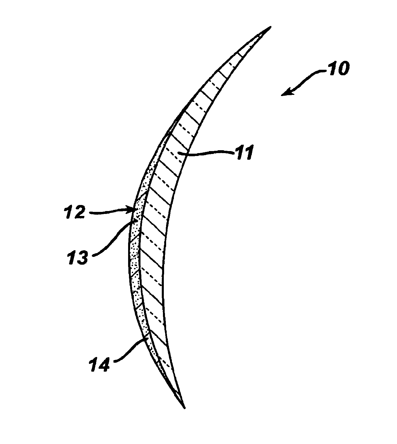
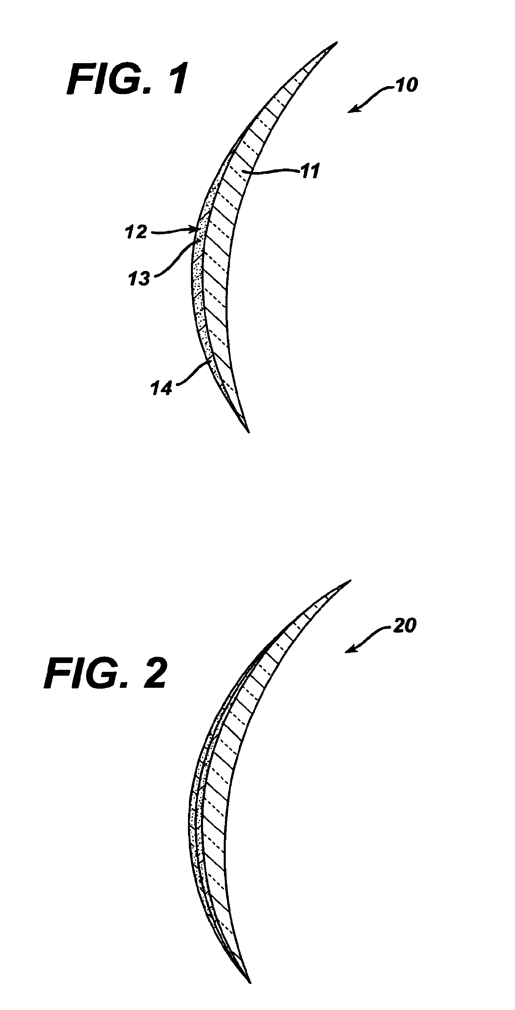
[0008]In the present invention, a method and lenses produced by the method are provided in which the center thickness is reduced compared to conventional multifocal lenses. In addition to a thinner lens, the method of the invention provides lenses having good impact resistance.

[0009]In one embodiment, the invention provides a method for manufacturing a multifocal lens comprising, consisting of, and consisting essentially of depositing on at least a portion of a surface of a lens substrate at least one layer of a surface forming amount of a high refractive index material, wherein the material is deposited under conditions suitable to form on the lens substrate surface a near vision zone, an intermediate vision zone, or a combination thereof. In another embodiment, the invention provides a multifocal lens produced by this method. For purposes of the invention a “high refractive index material” is a material having a refractive index of about 1.7 or greater.

[0010]The method of the inve...


PUM


Abstract

The present invention provides a method for the manufacture of thin multifocal lenses by deposition of a high refractive index material on a lens substrate.

Description

FIELD OF THE INVENTION[0001]The present invention relates to methods for manufacturing multifocal ophthalmic lenses. In particular, the invention provides a method for the manufacture of thin multifocal lenses using high refractive index materials.BACKGROUND OF THE INVENTION[0002]The use of ophthalmic lenses for the correction of ametropia is well known. For example, multifocal lenses, such as progressive addition lenses (“PAL's”), are used for the treatment of presbyopia. The progressive surface of a PAL provides far, intermediate, and near vision in a gradual, continuous progression of vertically increasing dioptric power from far to near focus, or top to bottom of the lens.[0003]PAL's are appealing to the wearer because PAL's are free of the visible ledges between the zones of differing dioptric power that are found in other multifocal lenses, such as bifocals and trifocals. However, an inherent disadvantage in PAL's is that, due to the incorporation of the power for the near vis...

Claims


Application Information

Patent Timeline
IPC IPC(8): G02C7/06G02C1/00G02C7/02G02C13/00
CPCG02C7/061G02C7/06
Inventor GUPTA, AMITAVAMCGINNIS, SEANKOKONASKI, WILLIAMGERLIGAND, PIERRE
Owner ESSILOR INT CIE GEN DOPTIQUE
Learn More