Image processing device and image display system

a technology of image processing and display system, which is applied in the direction of television system, signal generator with optical-mechanical scanning, instruments, etc., can solve the problems of insufficient suppression of motion blur effect, voltage too high to increase and limit in the voltage range where voltage may be applied to liquid crystal, etc., to achieve suppressing motion blur and increasing the response speed of liquid crystal

Inactive Publication Date: 2010-04-22
SONY CORP
View PDF11 Cites 28 Cited by
  • Summary
  • Abstract
  • Description
  • Claims
  • Application Information

AI Technical Summary

Benefits of technology

[0011]In view of the foregoing, it is desirable to provide an image processing device and an image display system capable of improving image quality of a moving image by suppressing a motion blur in a hold-type display device, while suppressing a cost increase.
[0012]According to an embodiment of the present invention, there is provided an image processing device processing image data provided from outside and outputting the image data to a hold type display device, the image processing device including a correction processing section performing a correction process to correct a pixel value in the image data for each pixel through performing a spatial LPF (low pass filter) process on the image data in a frame to be displayed in the display device according to a magnitude of a motion vector in the image data, the LPF process allowing a slope of a changing edge portion in the image data to be more gentle.
[0015]In the image processing device and the image display system according to the embodiments of the present invention, the pixel value in the image data is corrected for each pixel through performing the spatial LPF (low pass filter) process on the image data in the frame to be displayed according to the magnitude of the motion vector in the image data. Thereby, in the hold type display device, the motion blur (hold blur such as blur of a front edge, trailing of a rear edge, and delay of perception position) in the moving object, caused by the eye trace integration effect, is suppressed by an effect of substantial frame rate improvement with the interpolation in the spatial direction. Moreover, unlike the double speed drive technique of the existing art (interpolation in the temporal direction), since it is unnecessary to change the device itself, an issue of cost increase does not occur. Moreover, unlike the overdrive technique of the existing art, the motion blur is sufficiently suppressed in the gradation change in the region other than the region of the middle gradation.
[0016]In the image processing device and the image display system according to the embodiments of the present invention, the correction processing section preferably performs the correction process through executing a spatial HPF (high pass filter) process as well as the LPF process on the image data in the frame to be displayed, according to the magnitude of the motion vector, the HPF process allowing an overshoot region and an undershoot region to be provided in a vicinity of both ends of the changing edge portion in the image data. In the case of such a configuration, with a combination of the overshoot region and the undershoot region provided by the HPF process, the liquid crystal response is improved. Thus, the motion blur such as a blur of the edge, and trailing of the edge caused by the luminance change from the middle gradation to the middle gradation, and the delay in the fall response is suppressed. Therefore, the motion blur in the hold type display device is more efficiently suppressed, and the image quality of the moving image more improves.
[0017]According to the image processing device and the image display system of the embodiments of the present invention, the pixel value in the image data is corrected for each pixel through performing a spatial LPF (low pass filter) process on the image data in the frame to be displayed according to the magnitude of a motion vector in the image data. Thus, the eye trace integration effect is suppressed by the effect of substantial frame rate improvement with the interpolation in the spatial direction, and the motion blur is suppressed. Moreover, unlike the existing art, the issue of cost increase may be prevented, and the motion blur is sufficiently suppressed in the gradation change in the region other than the region of the middle gradation. Therefore, it is possible to improve the image quality of the moving image by suppressing the motion blur in the hold type display device, while suppressing the cost increase.

Problems solved by technology

However, in the overdrive technique, there is a limit in a voltage range where the voltage may be applied to the liquid crystal.
Thus, for example, in the case where the target voltage of a white display, a black display, or the like is close to the limit in the voltage range (the case of a gradation change in a high gradation region and a low gradation region), there is an issue that the voltage sufficiently high to increase the response speed of the liquid crystal may not be applied, and the effect of suppressing the motion blur may not be sufficiently exhibited.
When utilizing only the overdrive technique, there is such an issue that the luminance transition to the instructed luminance value may not be realized in one frame, in consideration of the response characteristics of the liquid crystal.
However, since a drive frequency of a display driver driving a display device increases by increasing the display frequency, there are issues that shortage of electric charges, an increase in the number of ICs and terminals of connectors, an increase in a substrate area, heat generation, an increase in EMI (electro magnetic interference), or the like occurs, and this may be a reason of a cost increase.

Method used


Image

  • Image processing device and image display system
  • Image processing device and image display system
  • Image processing device and image display system

Examples


first embodiment

1. First Embodiment

Improvement Measures for a Motion Blur

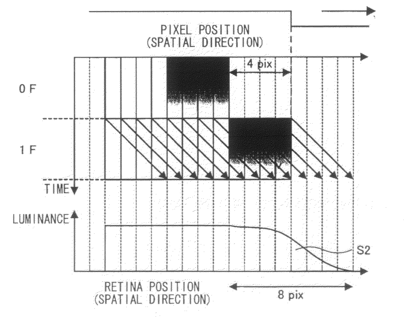
[0081]Before describing a preferred embodiment (first embodiment) of the present invention, the description will be made on a course in which the present inventors has conceived an image processing device according to the embodiment of the present invention, as the improvement measures for the motion blur in a hold type display device such as a liquid crystal display device.

[0082]As described above, in the hold type display device, a motion blur such as blur of a front edge, trailing of a rear edge, and delay of perception position occurs in a moving object. In the existing art, it is considered that the motion blur is caused by slowness of a response speed of a display element of liquid crystal or the like. Thus, an overdrive technique is utilized as the measures for improving the motion blur in the hold type display device. When this overdrive technique is utilized, it is possible to increase the response speed of the displa...

second embodiment

[0193]Next, a second embodiment of the present invention will be described. Same reference numerals as in the above first embodiment are used to indicate substantially identical components; thereby the description is appropriately omitted.

Configuration of Whole Image Processing Device

[0194]FIG. 19 illustrates the block configuration of the image processing device (an image processing device 300) according to the second embodiment of the present invention. The image processing device 300 includes a high frame rate conversion section 31, a moving image blur characteristics detection section 32, and a moving image blur improvement process section 33. The configuration of the display device in the image display system according to the second embodiment is similar to that of the display device 200 in the image display system 10 according to the first embodiment illustrated in FIG. 11, thereby the description is omitted.

[0195]The high frame rate conversion section 31 performs the high fra...


PUM


Abstract

The present invention provides an image processing device and an image display system achieving image quality improvement in moving picture by suppressing a motion blur in a hold-type display device, while maintaining low cost. The image processing device processes image data provided from outside and outputting the image data to a hold type display device. The image processing device includes a correction processing section performing a correction process to correct a pixel value in the image data for each pixel through performing a spatial LPF (low pass filter) process on the image data in a frame to be displayed in the display device according to a magnitude of a motion vector in the image data, the spatial LPF process allowing a slope of a changing edge portion in the image data to be more gentle.

Description

BACKGROUND OF THE INVENTION[0001]1. Field of the Invention[0002]The present invention relates to an image processing device which processes an image data input from outside and outputs the image data to a hold type display device, and an image display system including the same.[0003]2. Description of the Related Art[0004]In recent years, a low-profile display such as a liquid crystal display (LCD) has been widely spread in substitution for a CRT (cathode ray tube), and a technique for a moving-image display on the LCD has attracted attention.[0005]Unlike an impulse type display device such as the CRT, when displaying the moving image in the hold type display device such as the LCD, a display of all pixels constituting a screen is held during a period from when a certain one in a plurality of frames or fields (hereafter, simply referred to as “frames”) constituting the moving image is specified to be displayed, until when a next frame is specified to be displayed. Thus, in the hold t...

Claims


Application Information

Patent Timeline
Patent Type & Authority Applications(United States)
IPC IPC(8): G06K9/40
CPCG09G3/3648G09G2320/0252G09G2320/0261G09G2320/0271H04N5/21G09G2340/16H04N5/142H04N5/144H04N5/145G09G2320/106
Inventor ARASHIMA, KENJIYANO, TOMOYANISHI, TORU
Owner SONY CORP
Why Eureka
Try Eureka